
Maker Projects
Hand Tool Only Woodwork
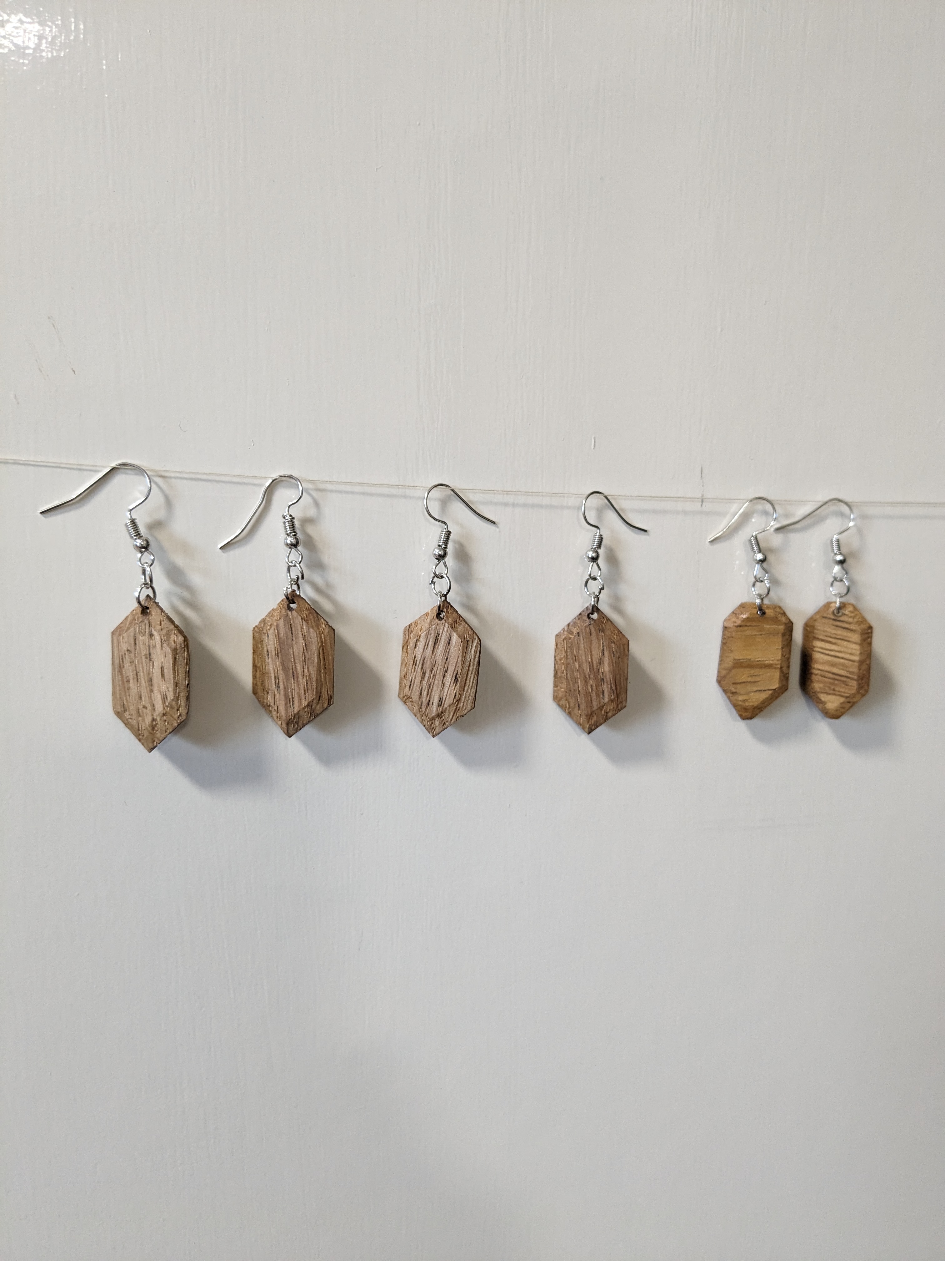
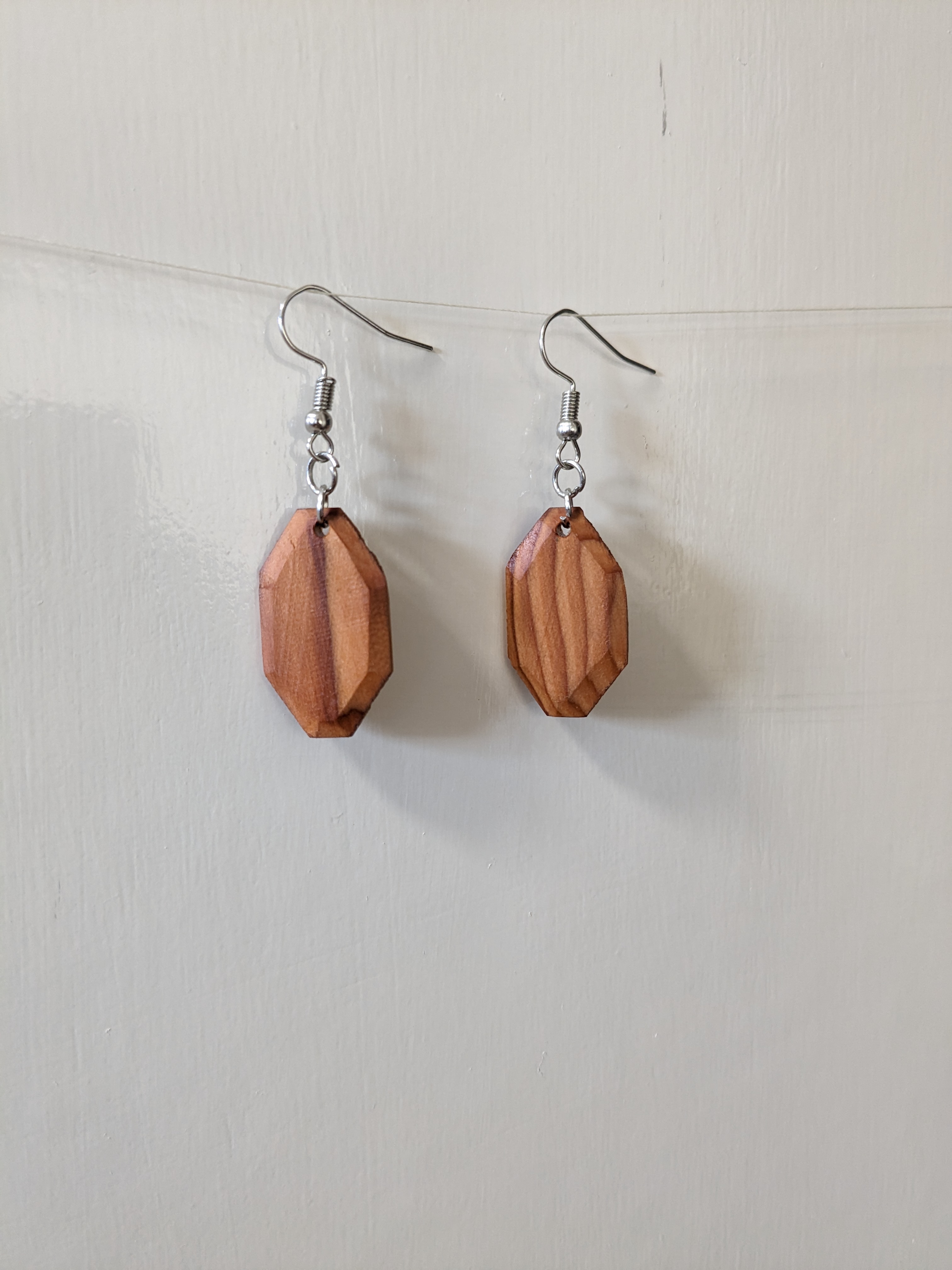
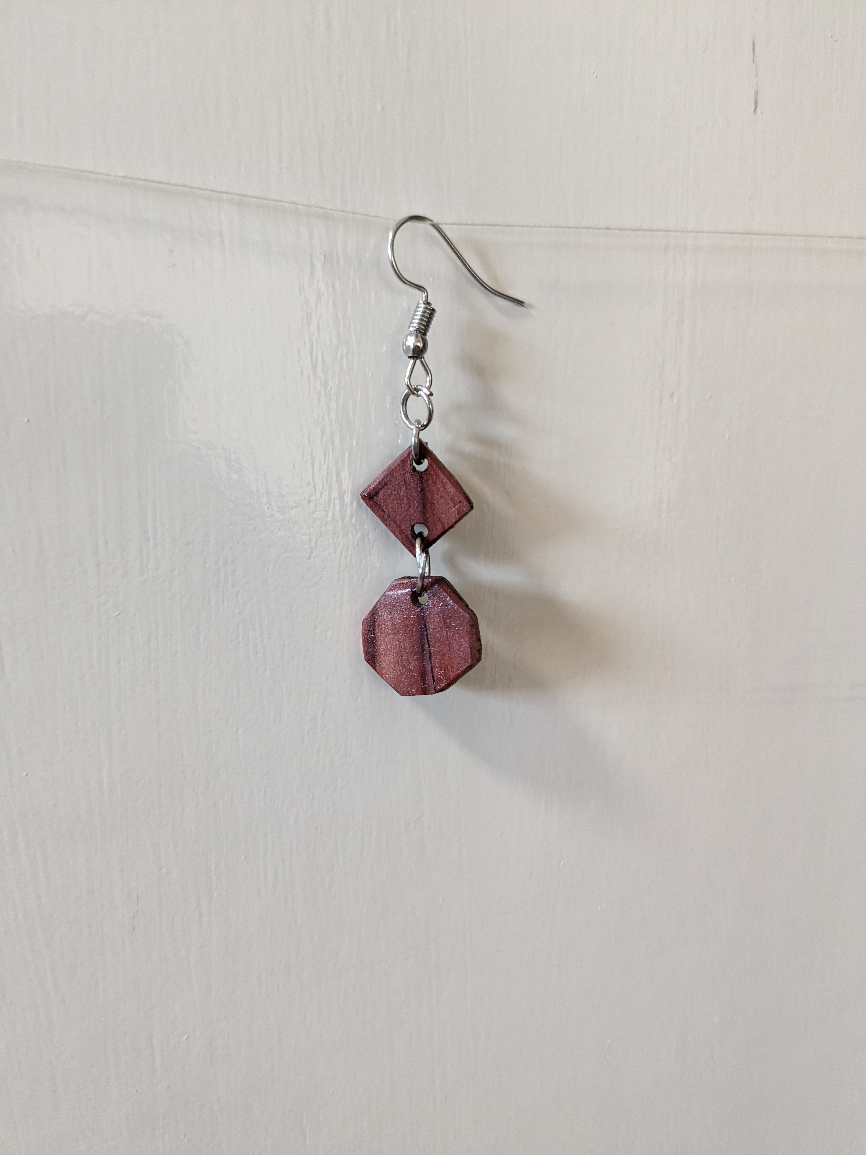
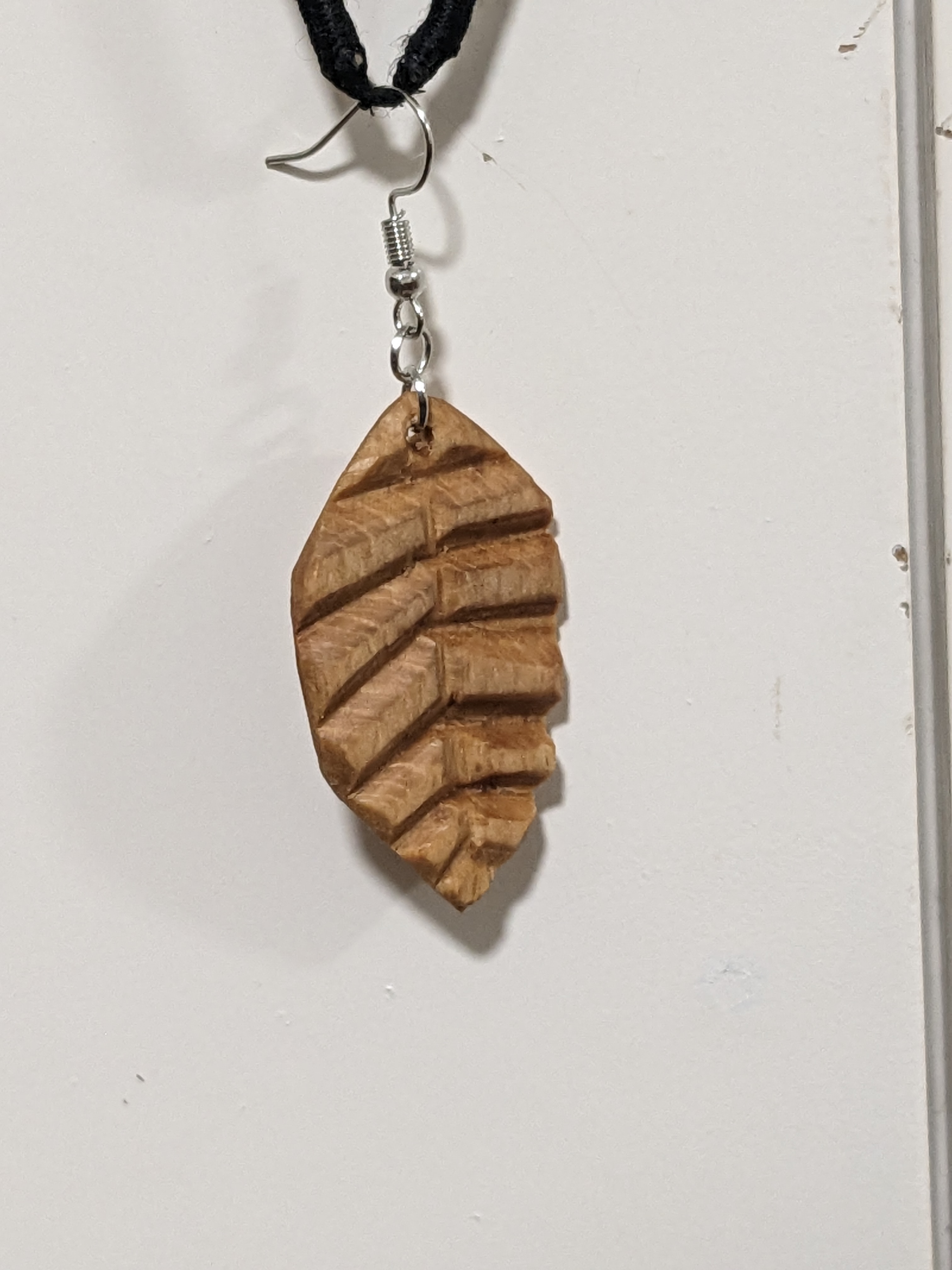
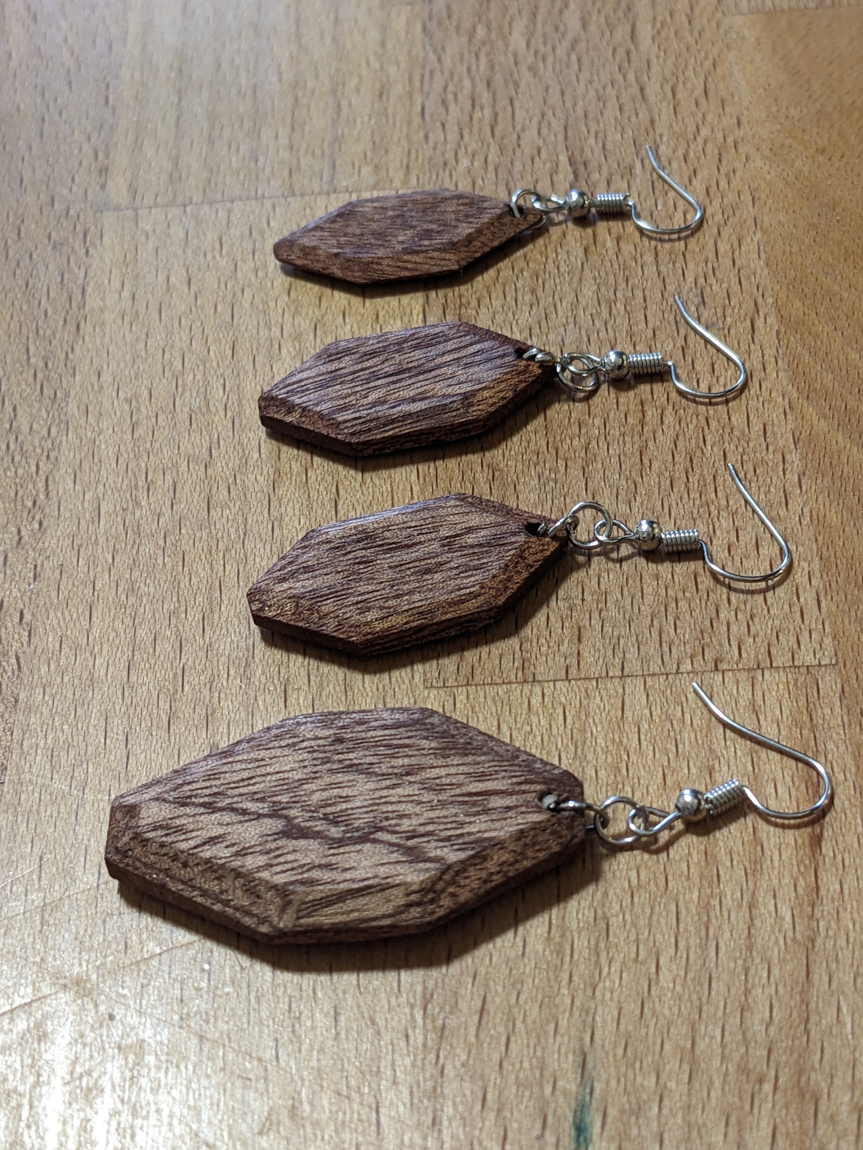
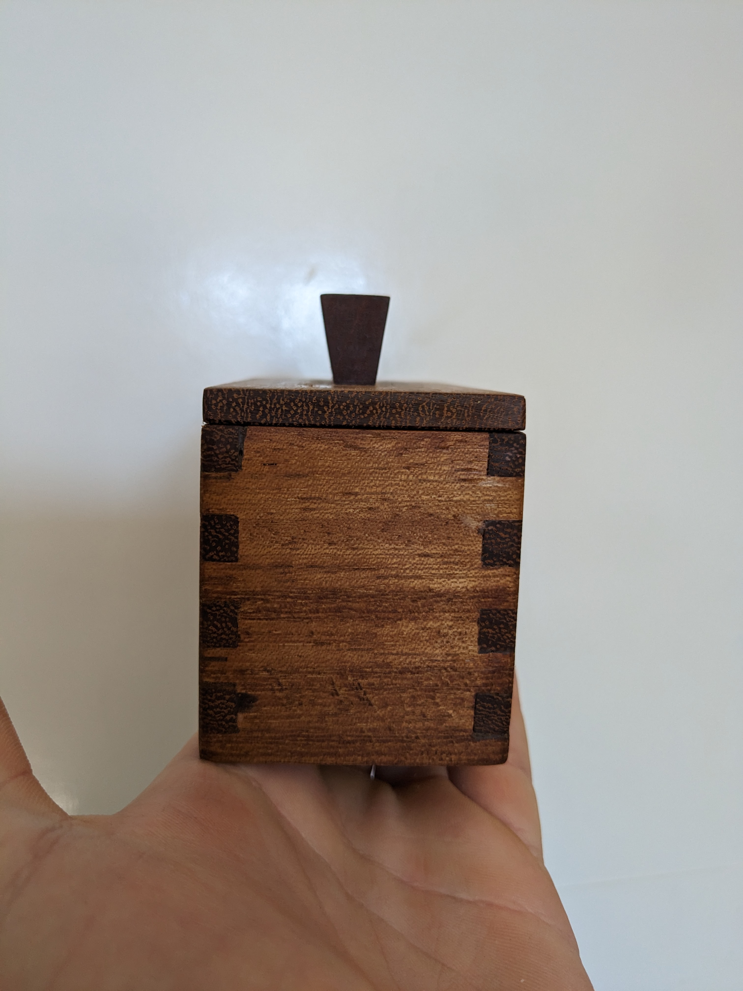
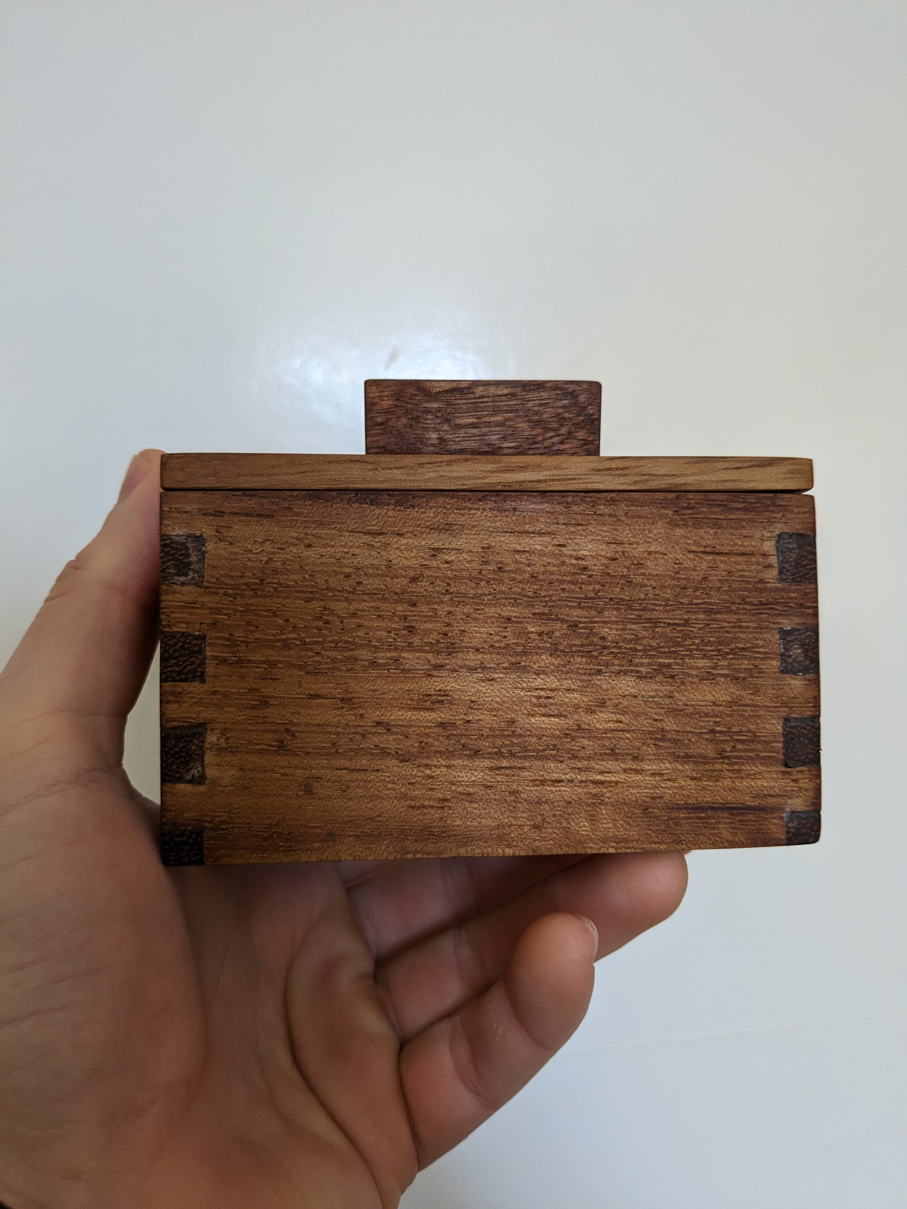
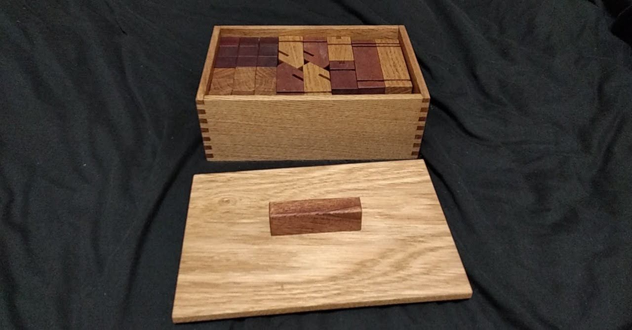
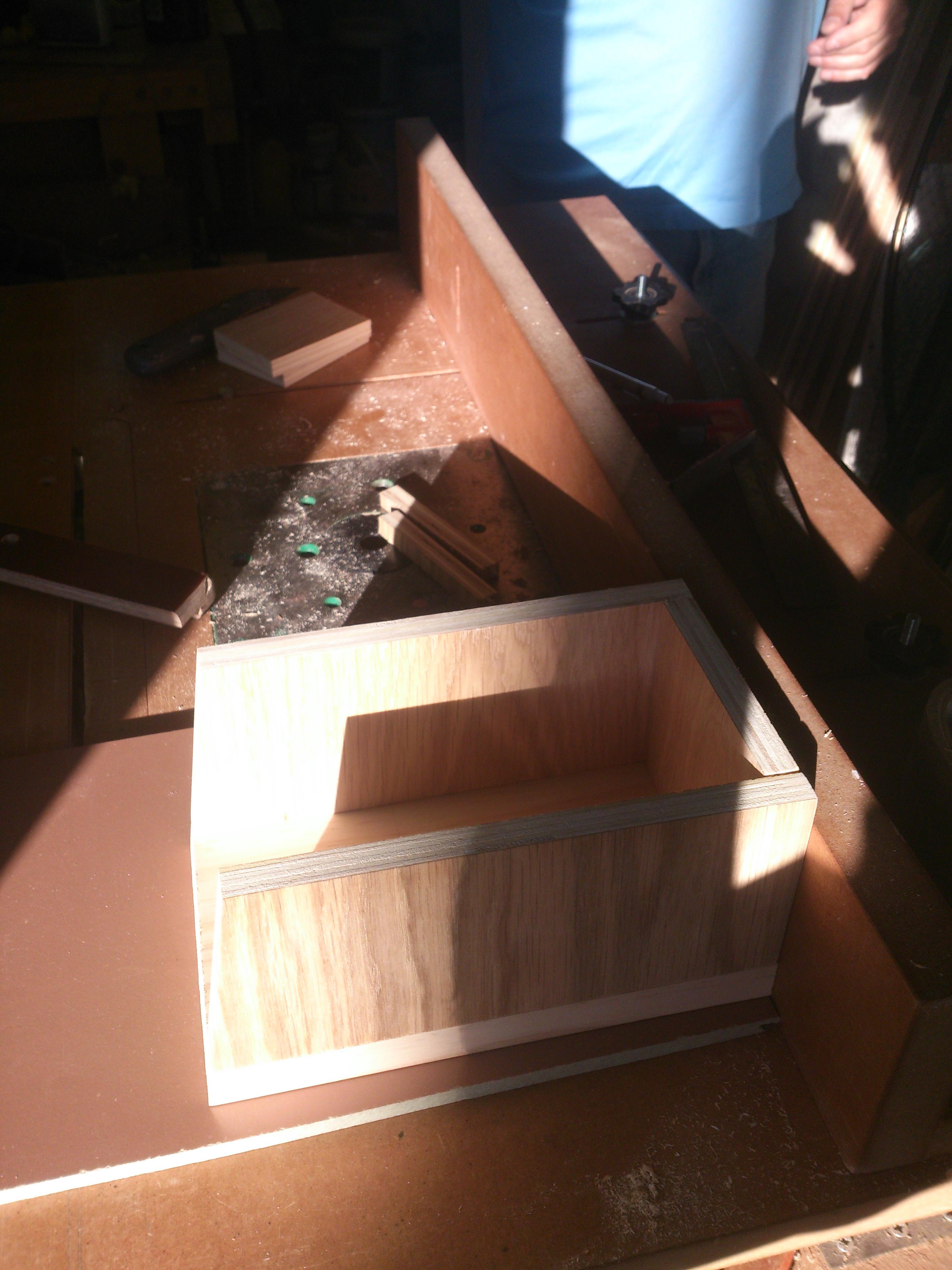
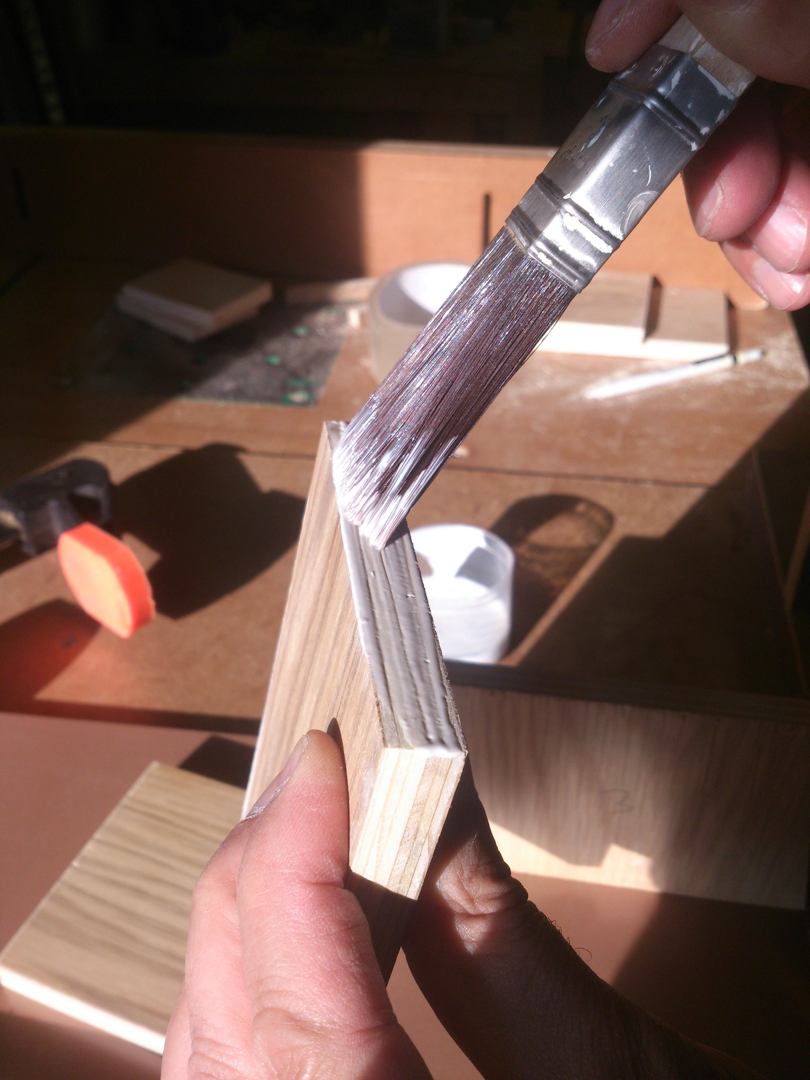
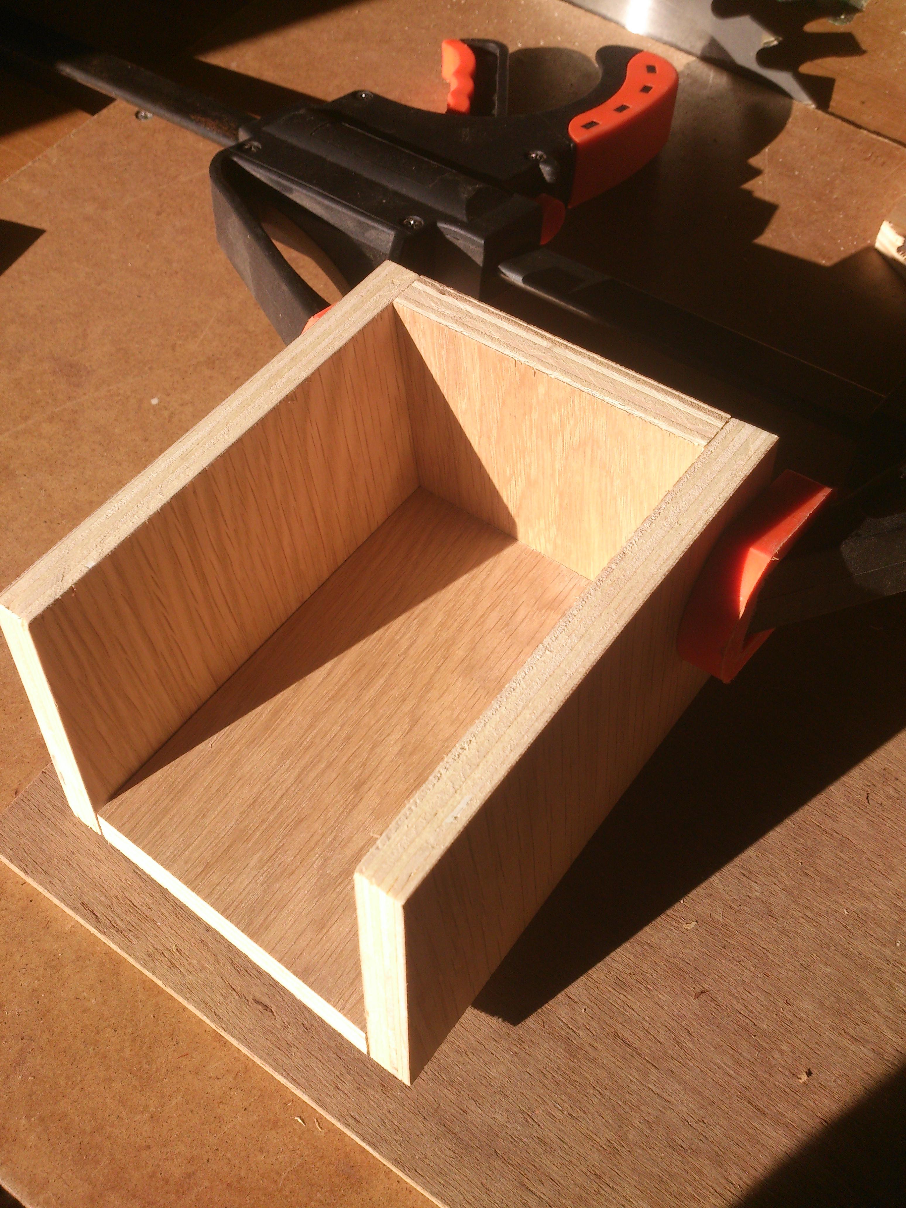
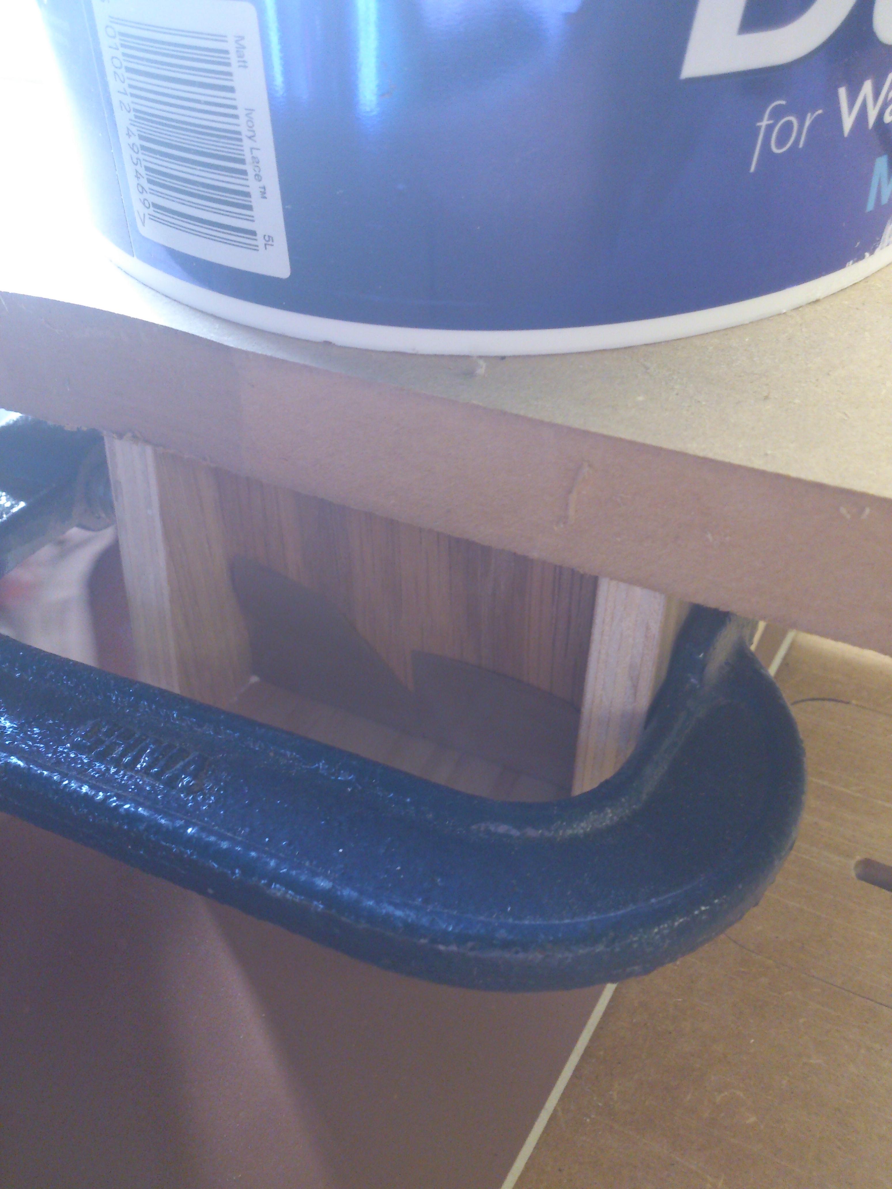
I have accrued a small collection of hand tools: a block plane, some pull saws and some cheap chisels. I wanted to use only these tools to make some small objects as a way to refine my skills. The images on the left show some simple earrings, some carved earrings and a box sized to store these.
Chess Board
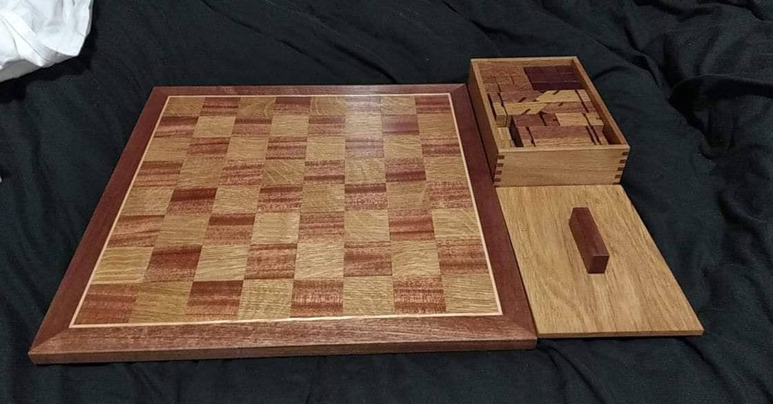
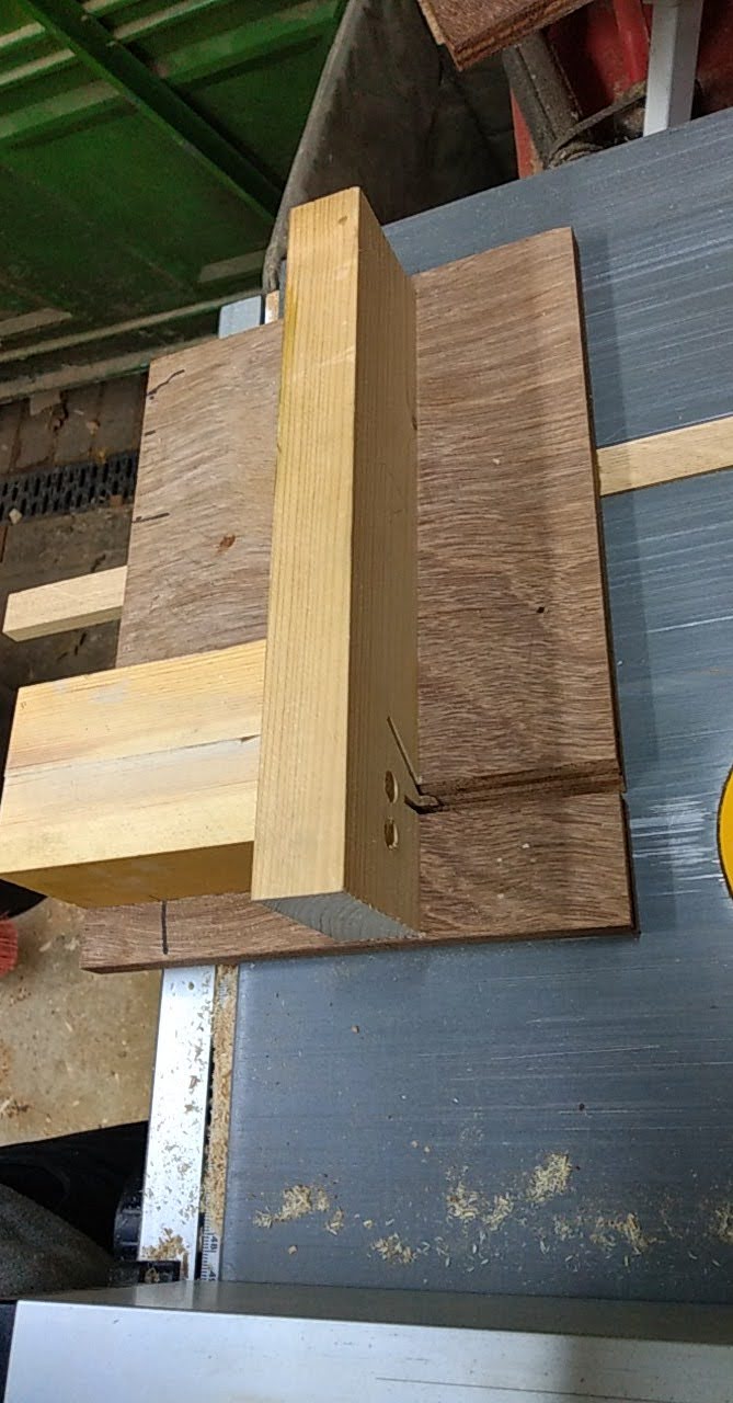
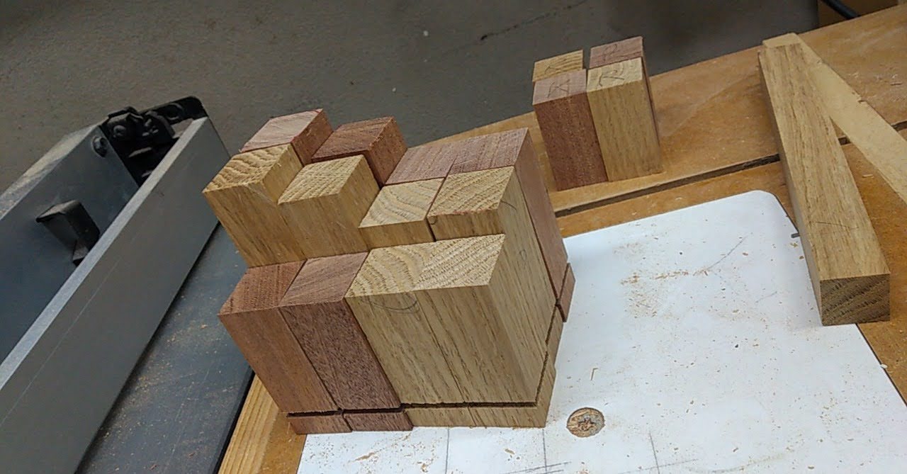
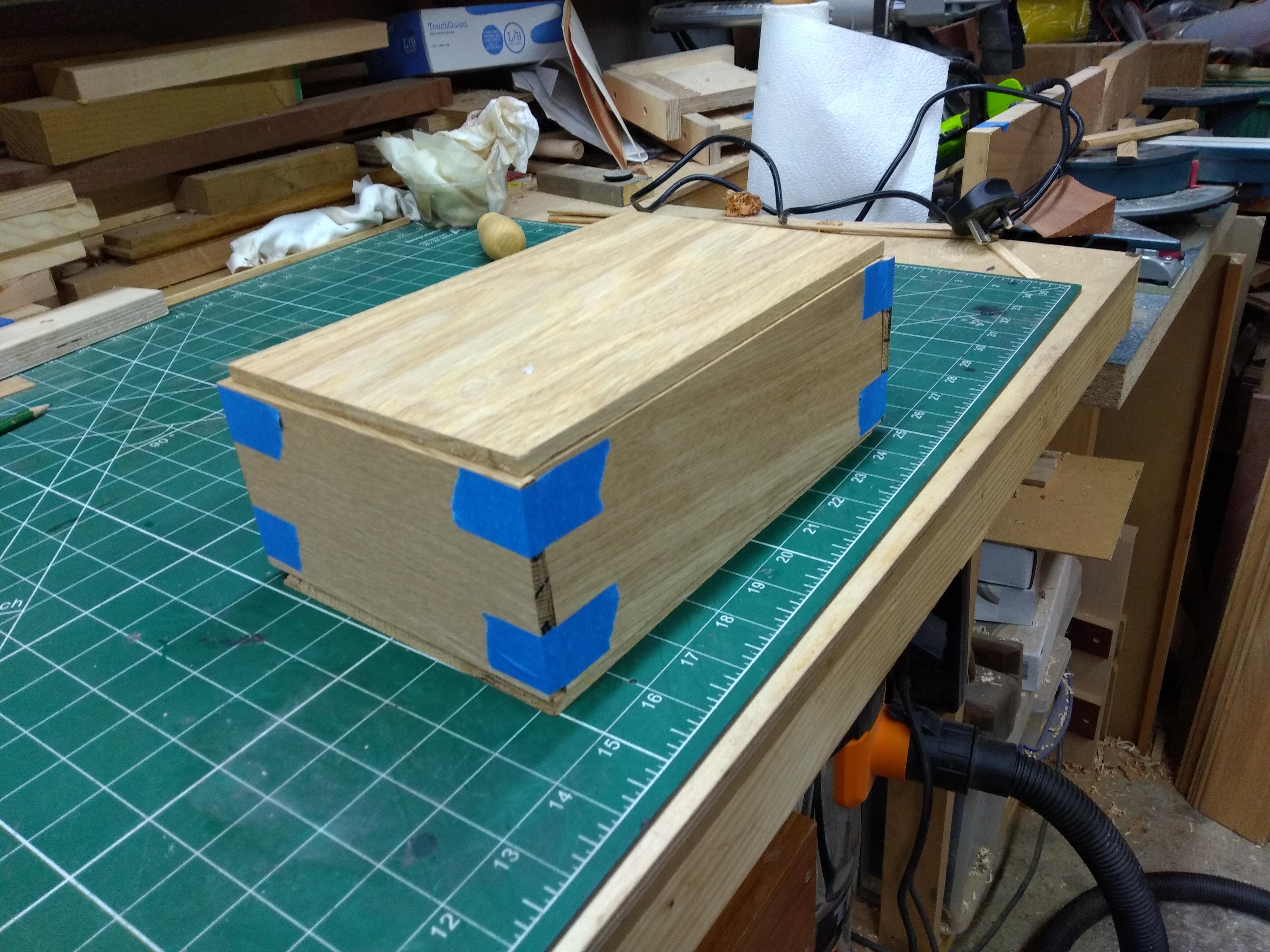
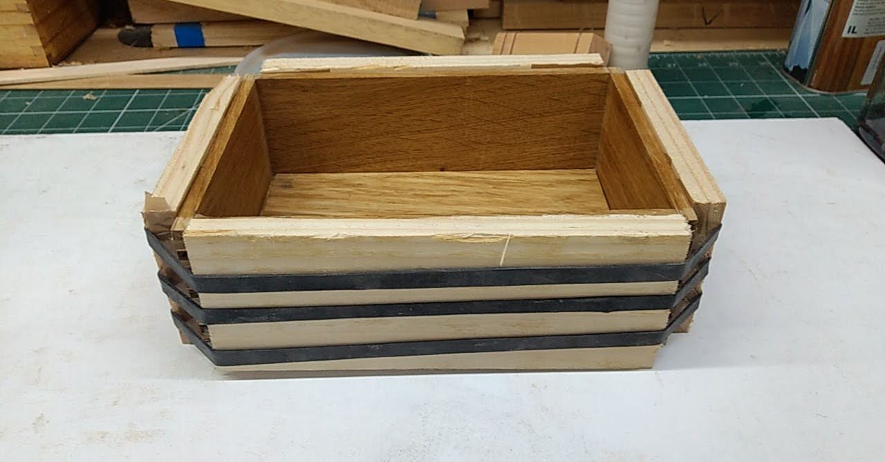
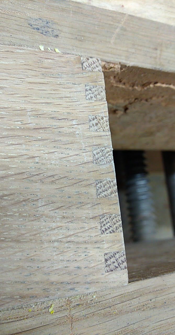
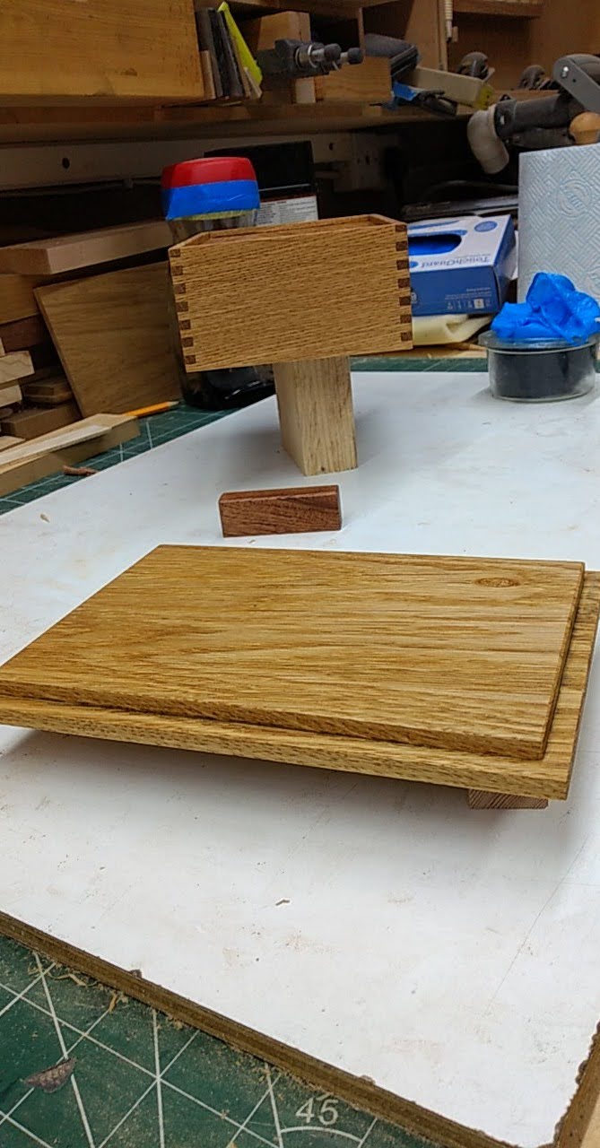
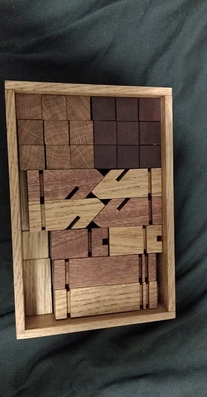
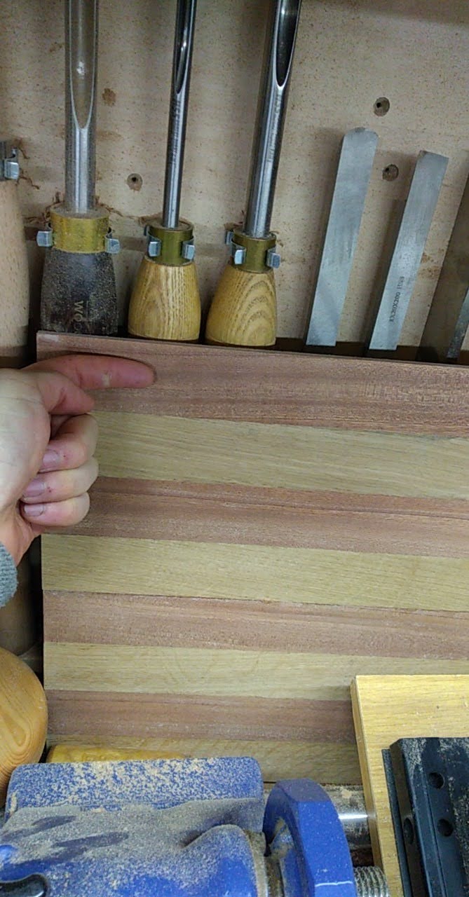
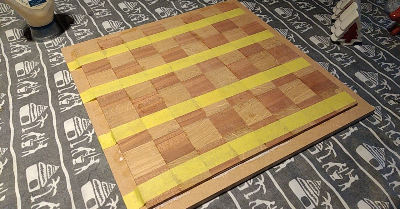
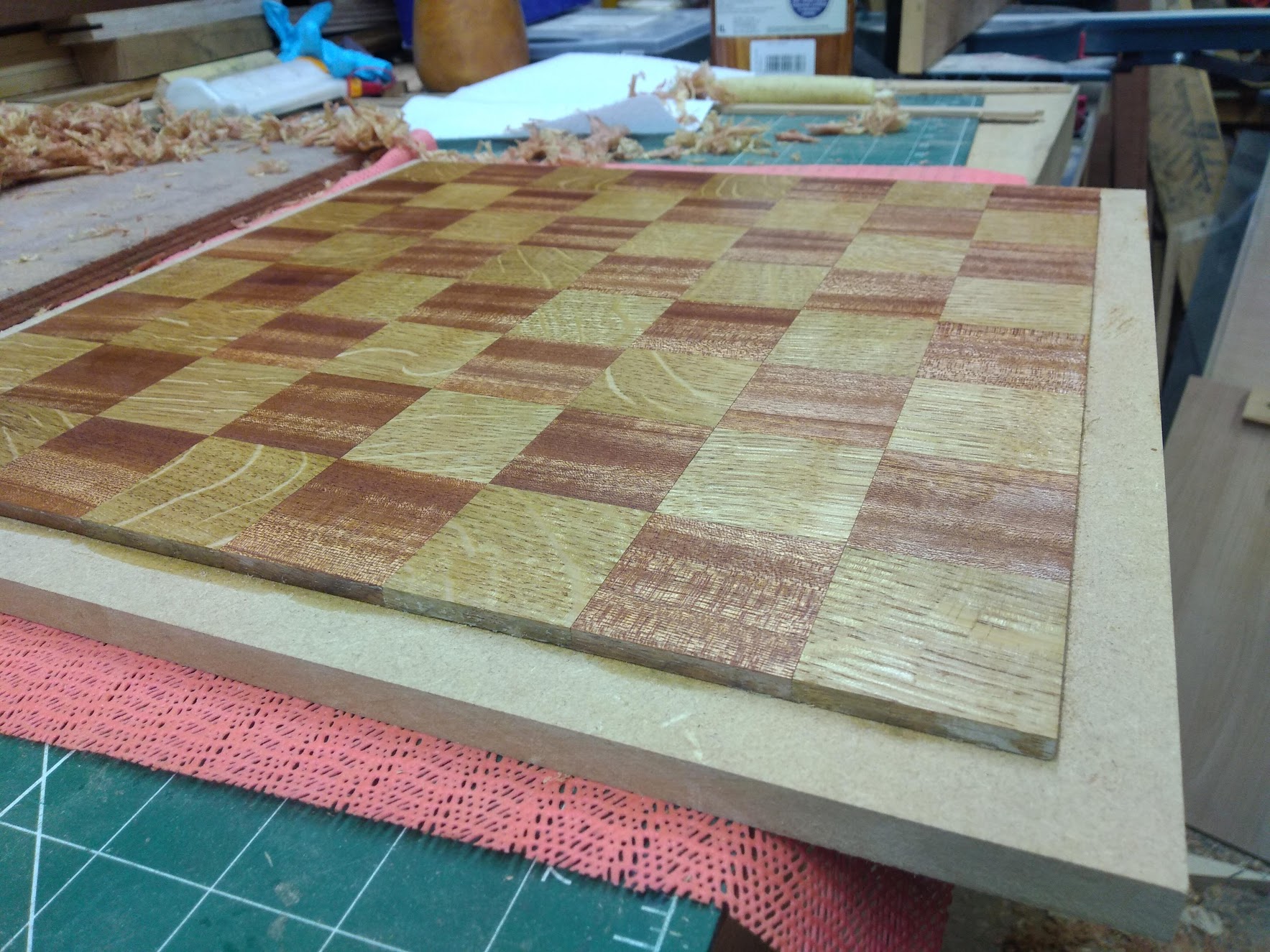
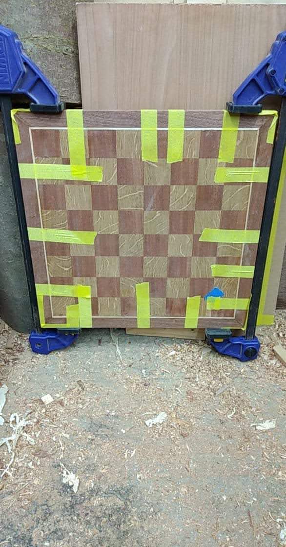
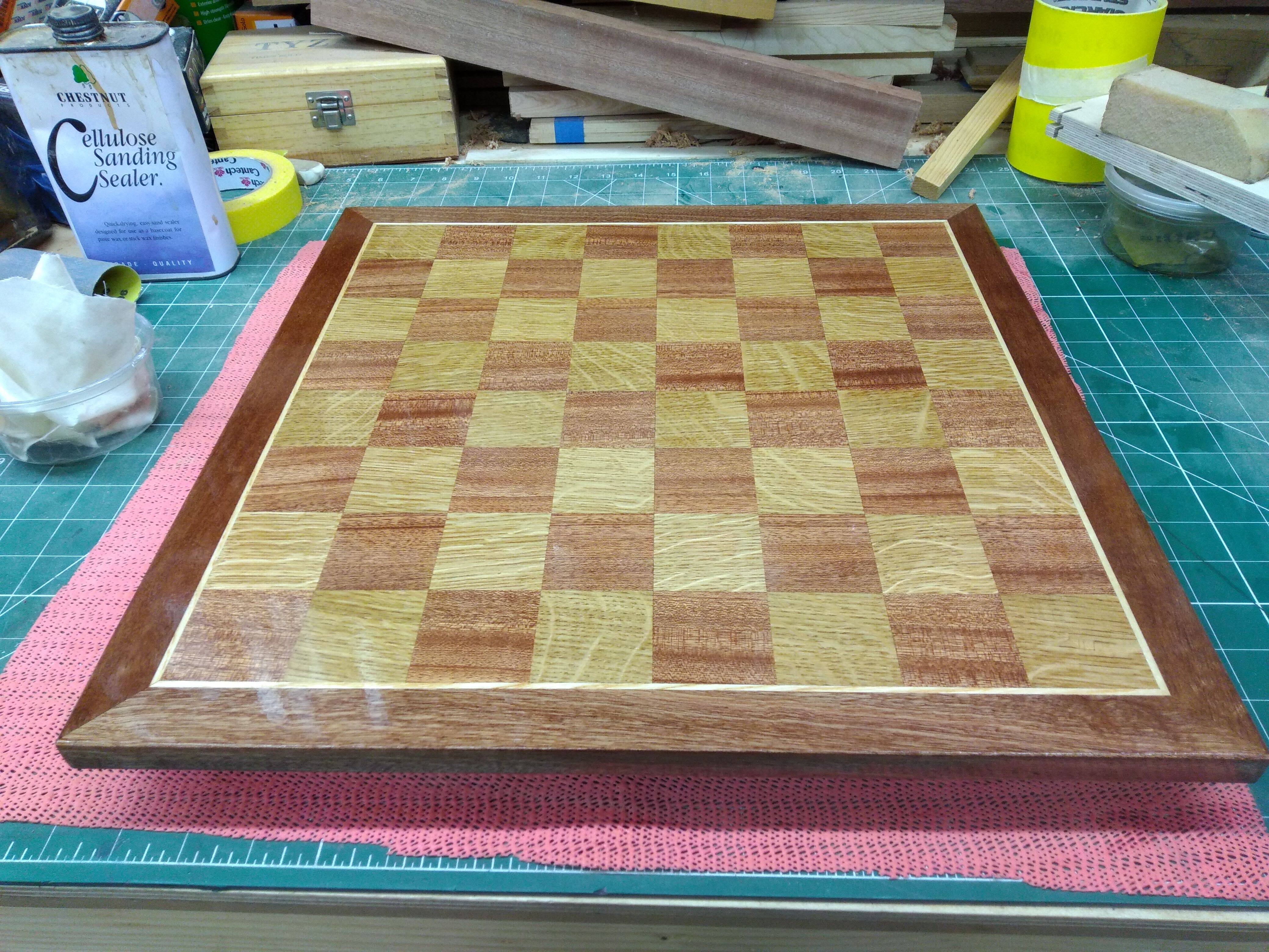
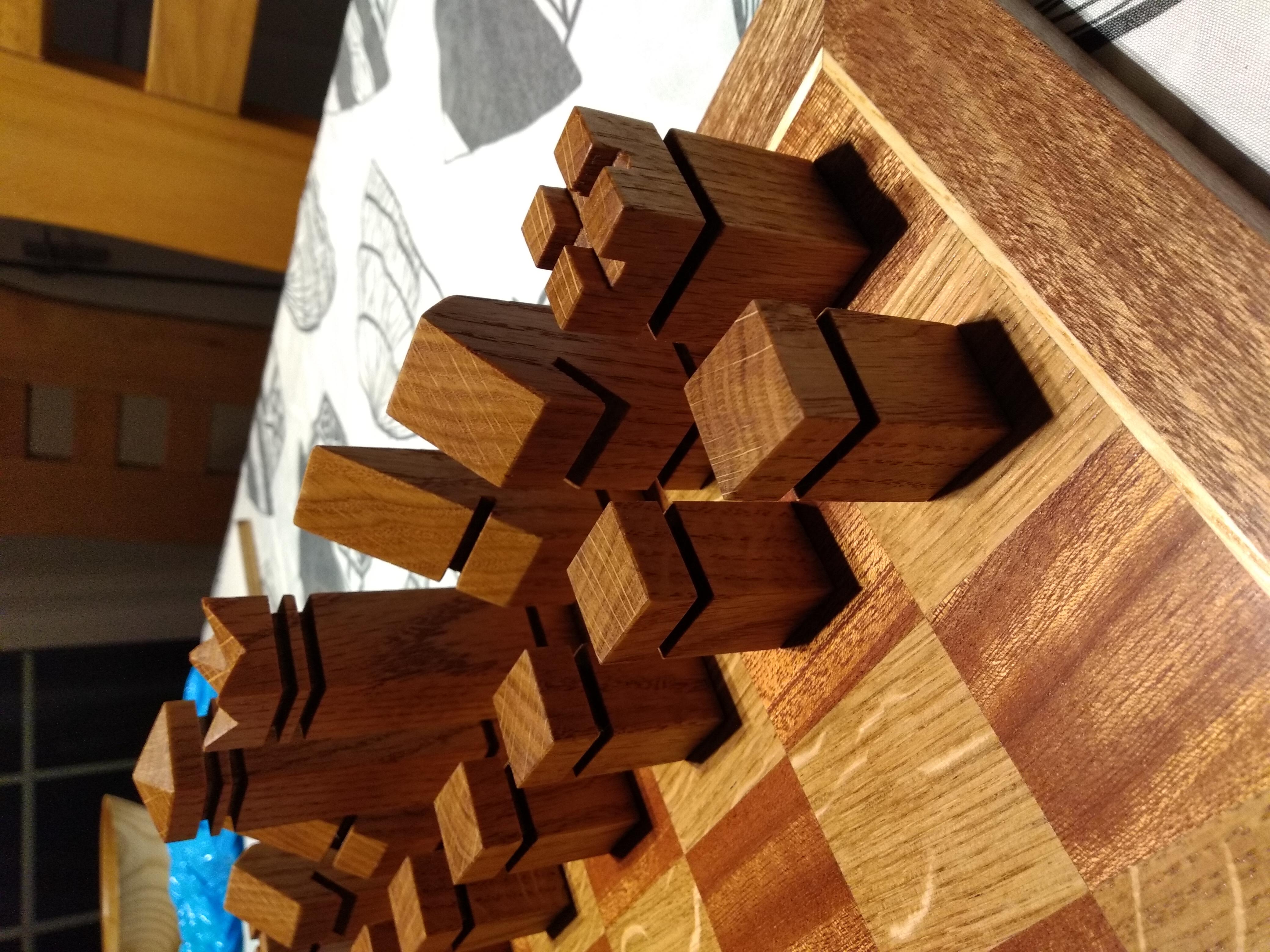
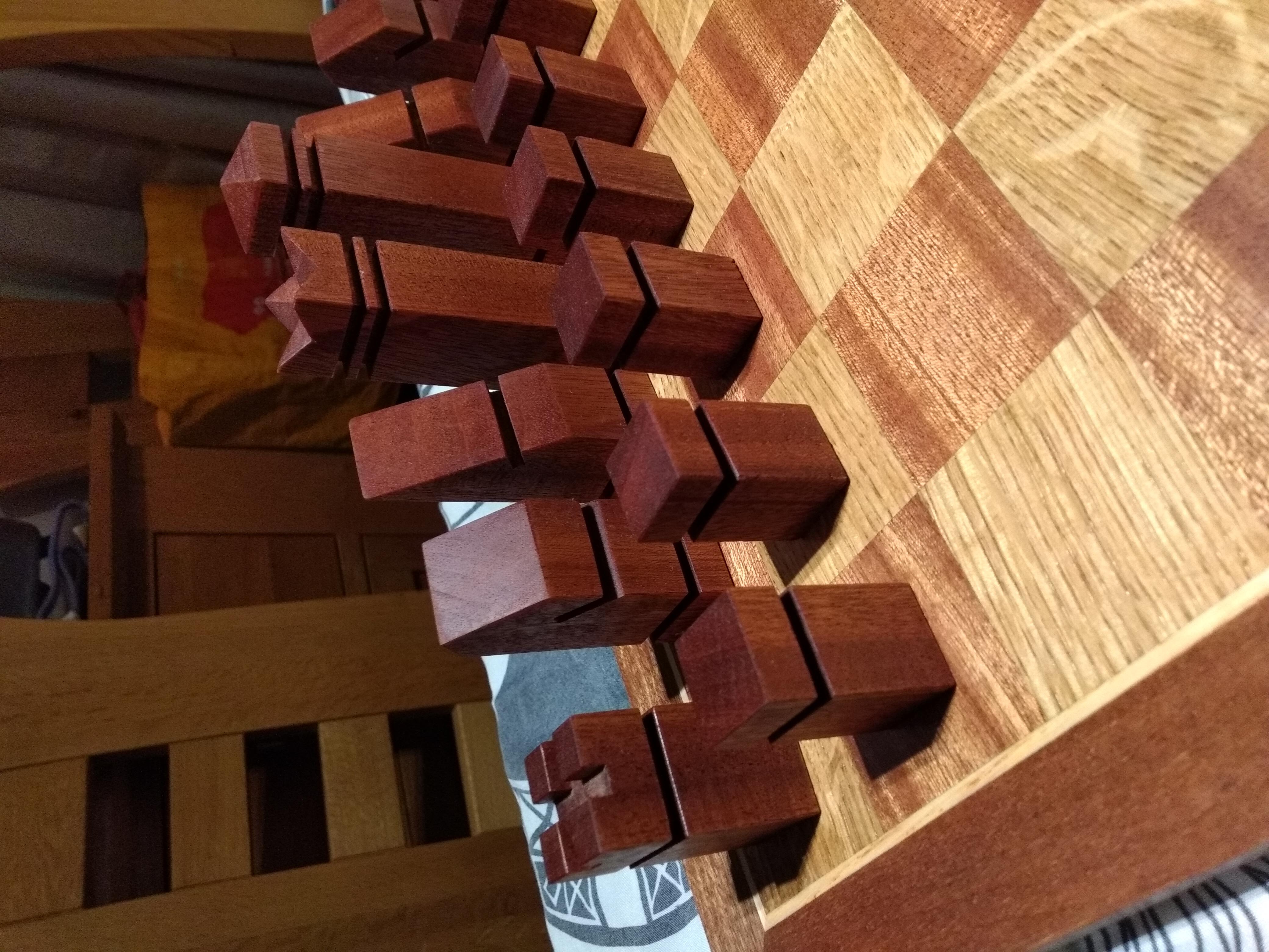
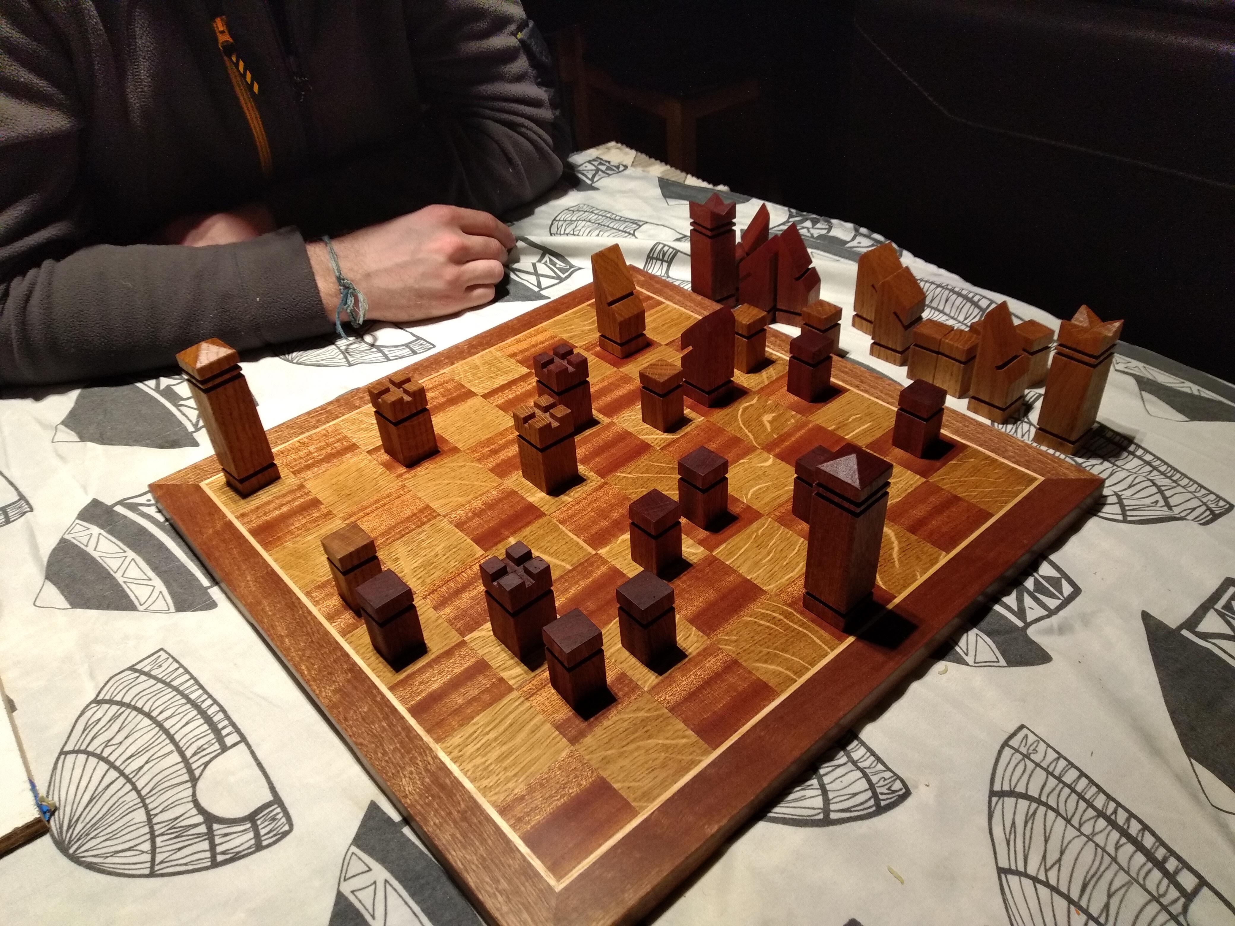
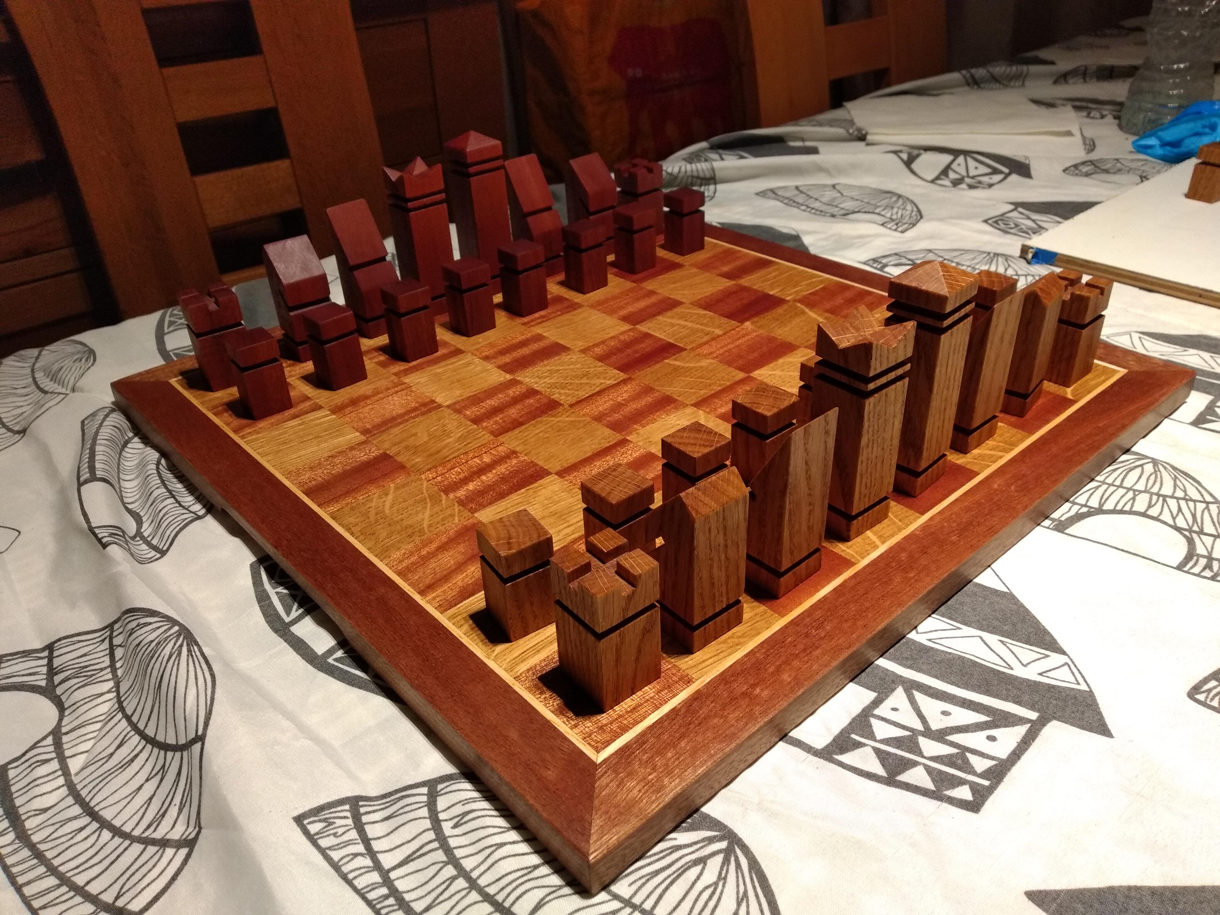
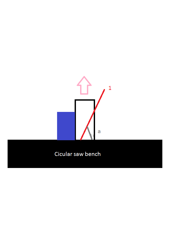
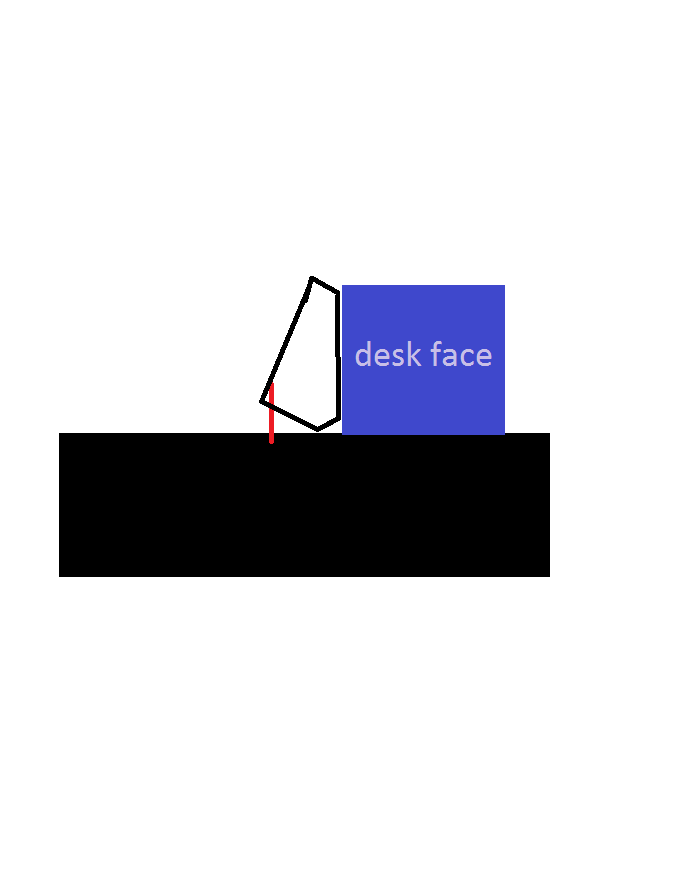
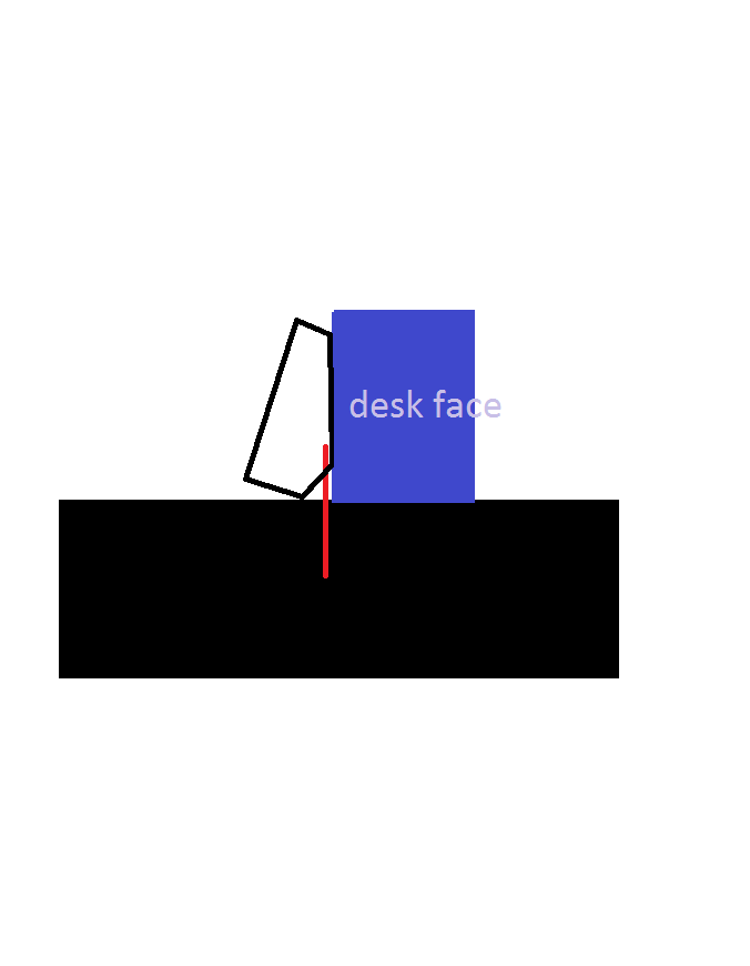
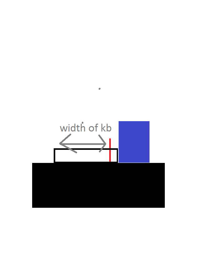
Despite not enjoying chess, I made this chess board for my colleagues to play on. This is to replace a small travel board they were using regularly at work (during their breaks only, naturally). The pieces are heavily inspired by this video where I took the same premise of making the pieces on the table saw but chose to modify the proportions. To choose the proportions, a parametric CAD design was drawn for each type of piece and multiple version were produced. Choosing the best of these, the parameters were tweaked further by hand until a preference for ratios was found. The board design is original, and the thin trim of ash is used to create contrast between the oak/sapele board and the sapele boarder. The squares are mounted to a 20 mm thick sheet of MDF to improve stability/prevent warping. A full model of the board was made using a 45 mm square size as the fixed parameter. The scale of the pieces was then adjusted until they looked good on the virtual board. When making a prototype for the king, it was clear there was a mistake so it was refined even further. In the end the pawns were 20 mm square profile and 25 mm square for the pieces. To store the material, a box was designed and made. The lid was friction fit but over time has shrunk to be slightly loose. Inserts and a sheet of felt ensure a snug fit. The board, box and material were made using only a thicknesser, table saw, hand planes and sand paper. Finished with danish oil and furniture wax.
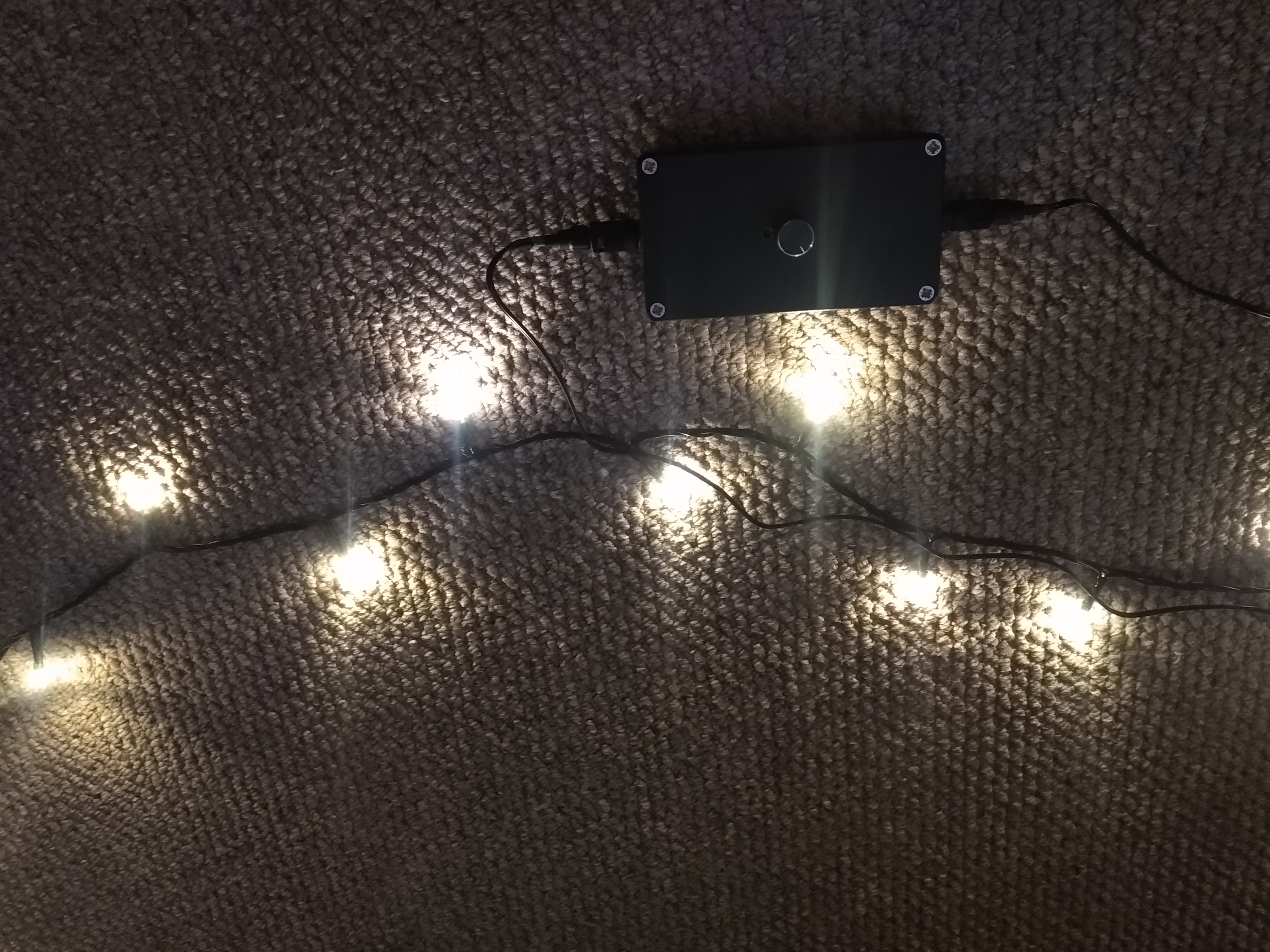
Dimmable Two Wire LED String Driver
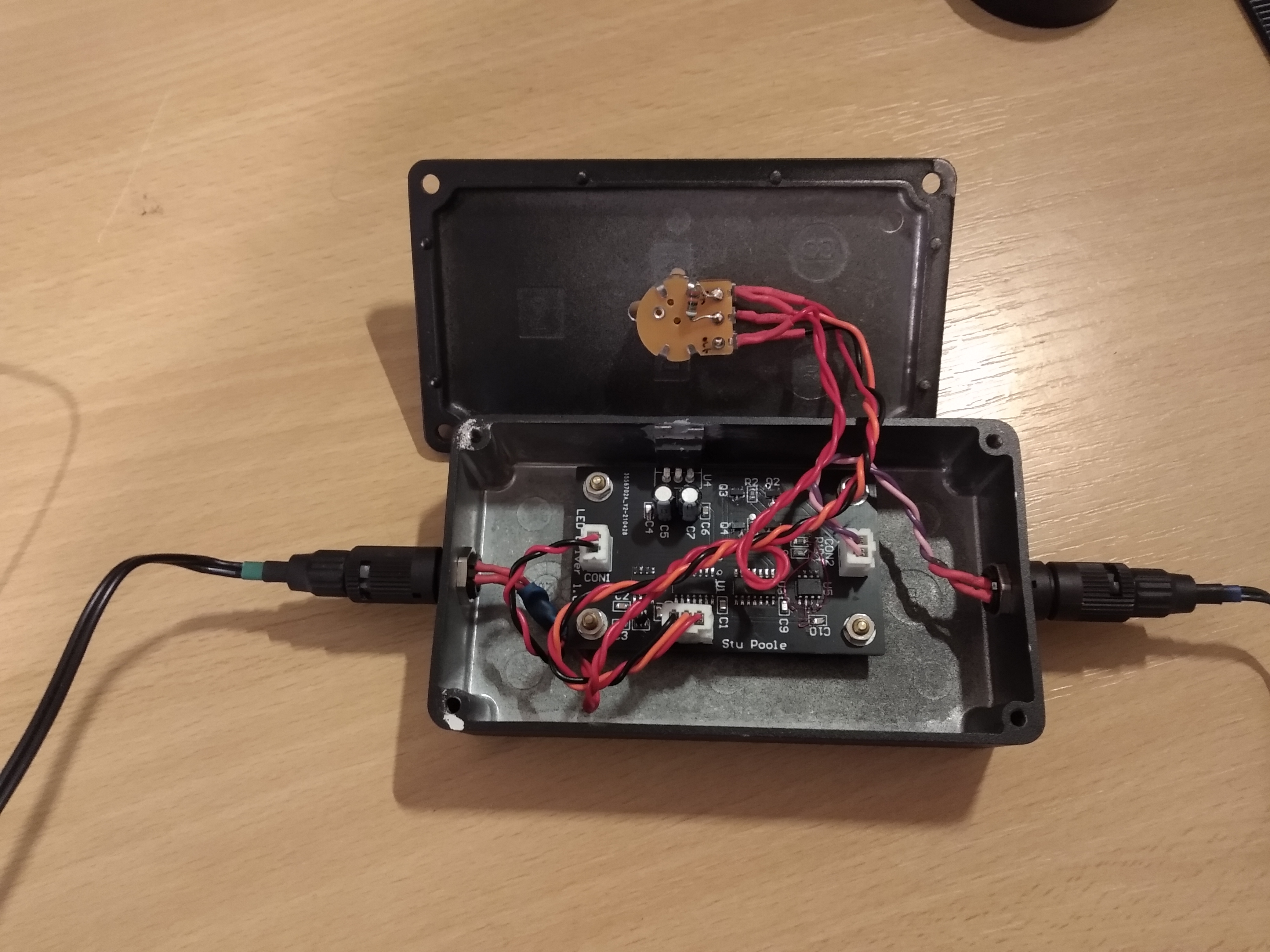
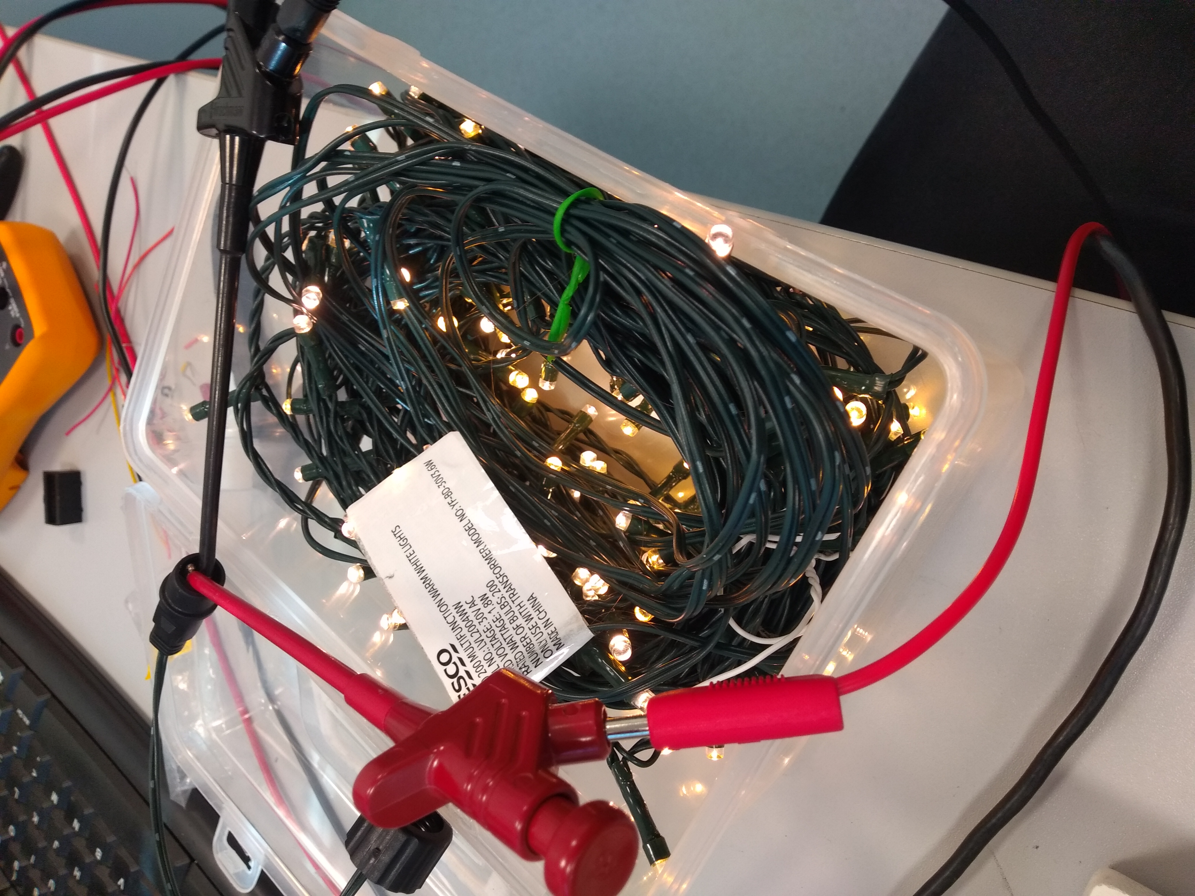
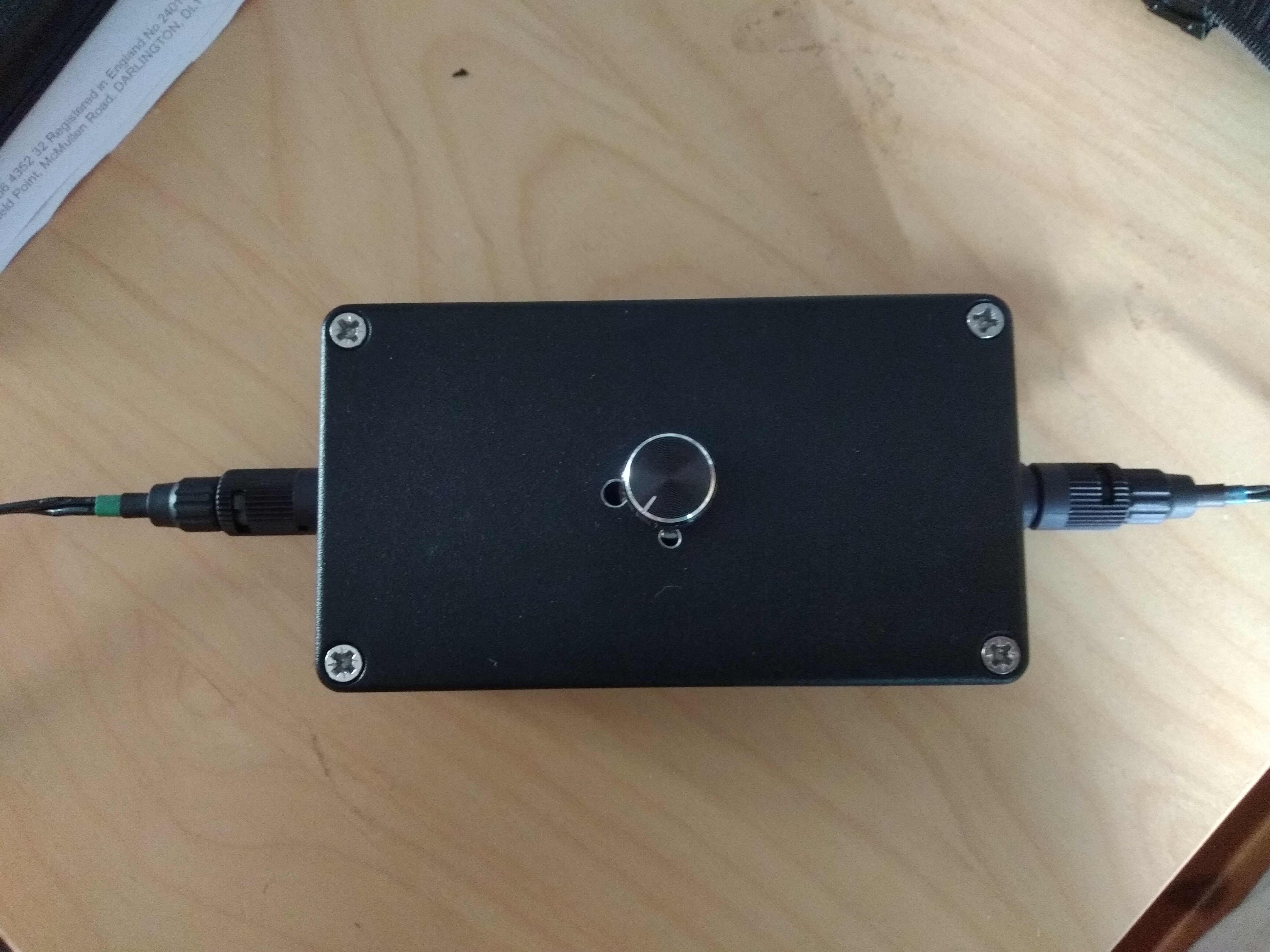
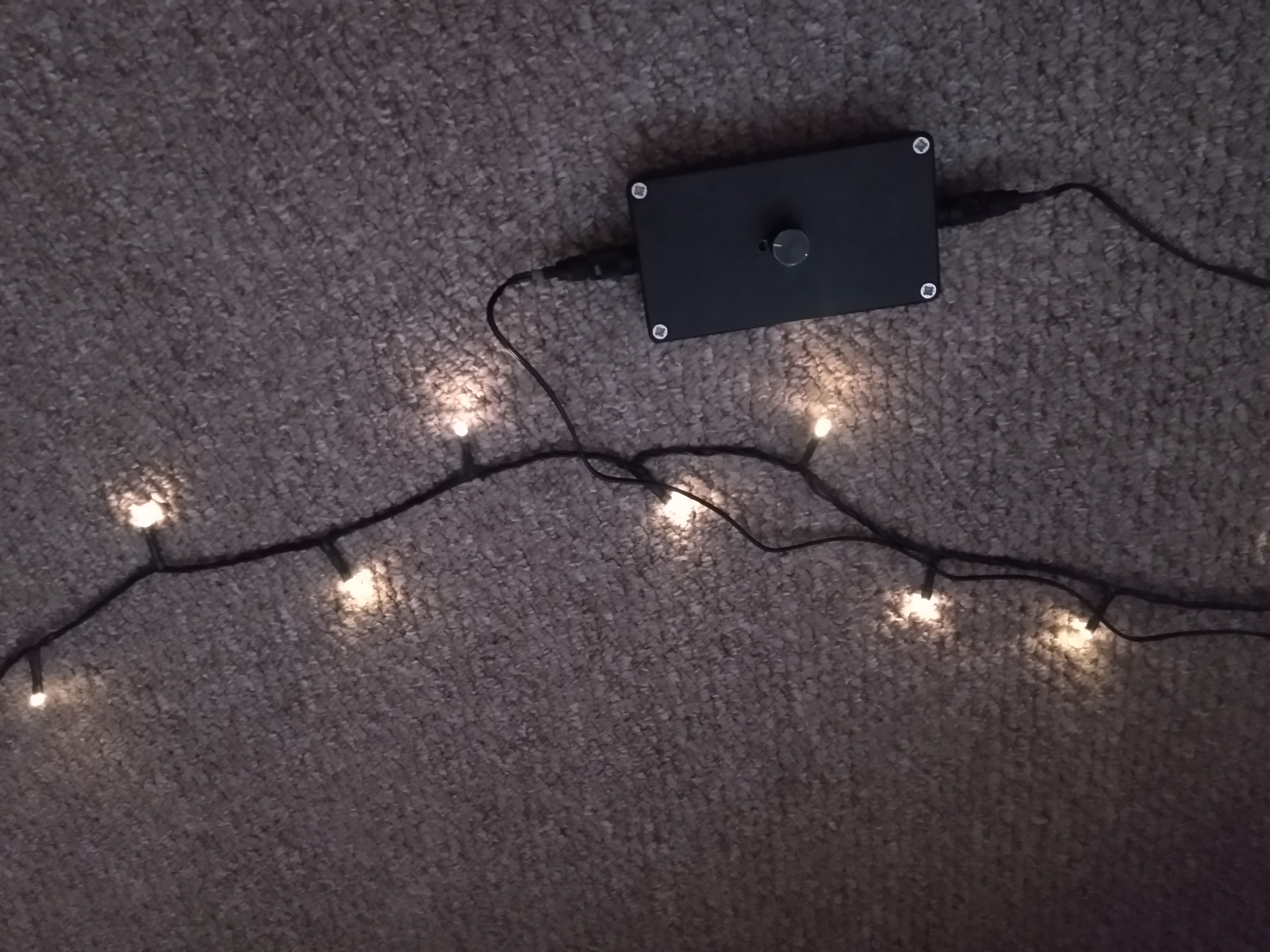
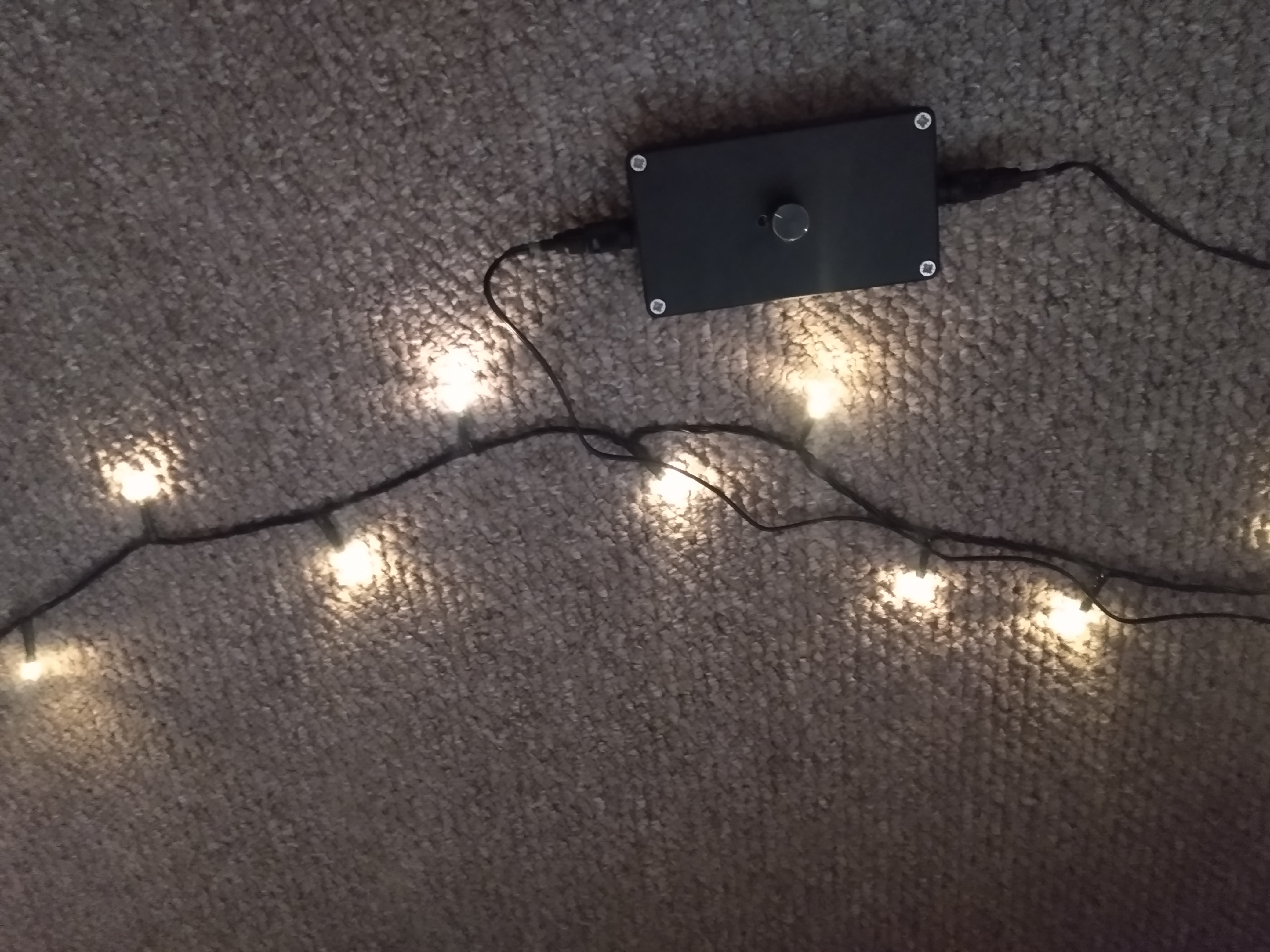
I bought some cheap fairy lights for my partner to use around a room to make the room feel cosy, unfortunately they it with the light of a thousand suns. I was worried they might, but I thought it would be simple to fix this with the addition of a resistor somewhere in the circuit but it turns out that these light are driver with two wires, not the typical three. For three wires, there is a ground lead and two separate control lines for each half of the lamps. For 2 wire control, the drive current polarity is swapped, with half the bulbs lighting with one current polarity and the other half with the other polarity (LEDs are Diodes after all). This complicates things because I want them all to be on and to be dimmer/dimmable. I decided to make a box with a knob.
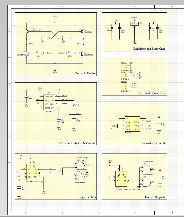
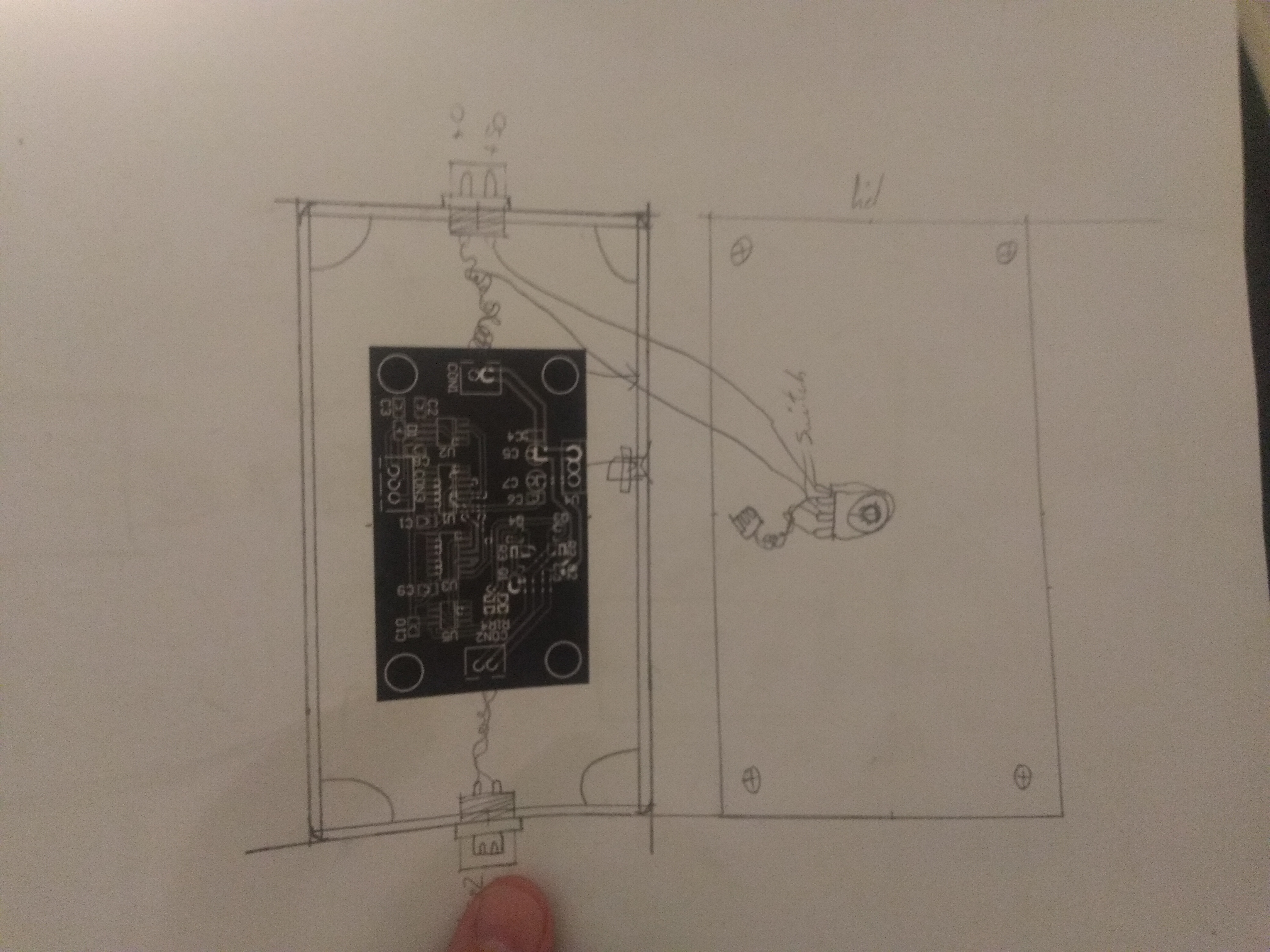
The circuit diagram is available below. The circuit's goal is to drive the LEDs in a way such that all the lamps are lit, and each channel is dimmed equally. A PWM signal with alternating polarity is the goal. To achieve this, we need an oscillating signal, preferably a square wave, which can swap between two polarities. I found that the original circuit for a very similar power supply used an H-bridge as shown in this diagram from this post. I can source all these parts easily, I only need to solve the DRV1 and DRV2 signals which must never both be on. To do this, a 555-timer in a constant period configuration was used, with a potentiometer to control the duty cycle. The resulting clock signal is passed to a toggle latch and a pair of AND gates, such that DRV1 is high when the latch Q is high AND the clock is high, and low otherwise. Similarly, the DRV2 signal is high when latch Q AND the clock is high, otherwise it is low. The 555 timer therefore controls how long the current is flowing and the latch controls the polarity of the current. The 30V supply will be external and a 5V linear regulator will be used to provide supply voltage for the logic.
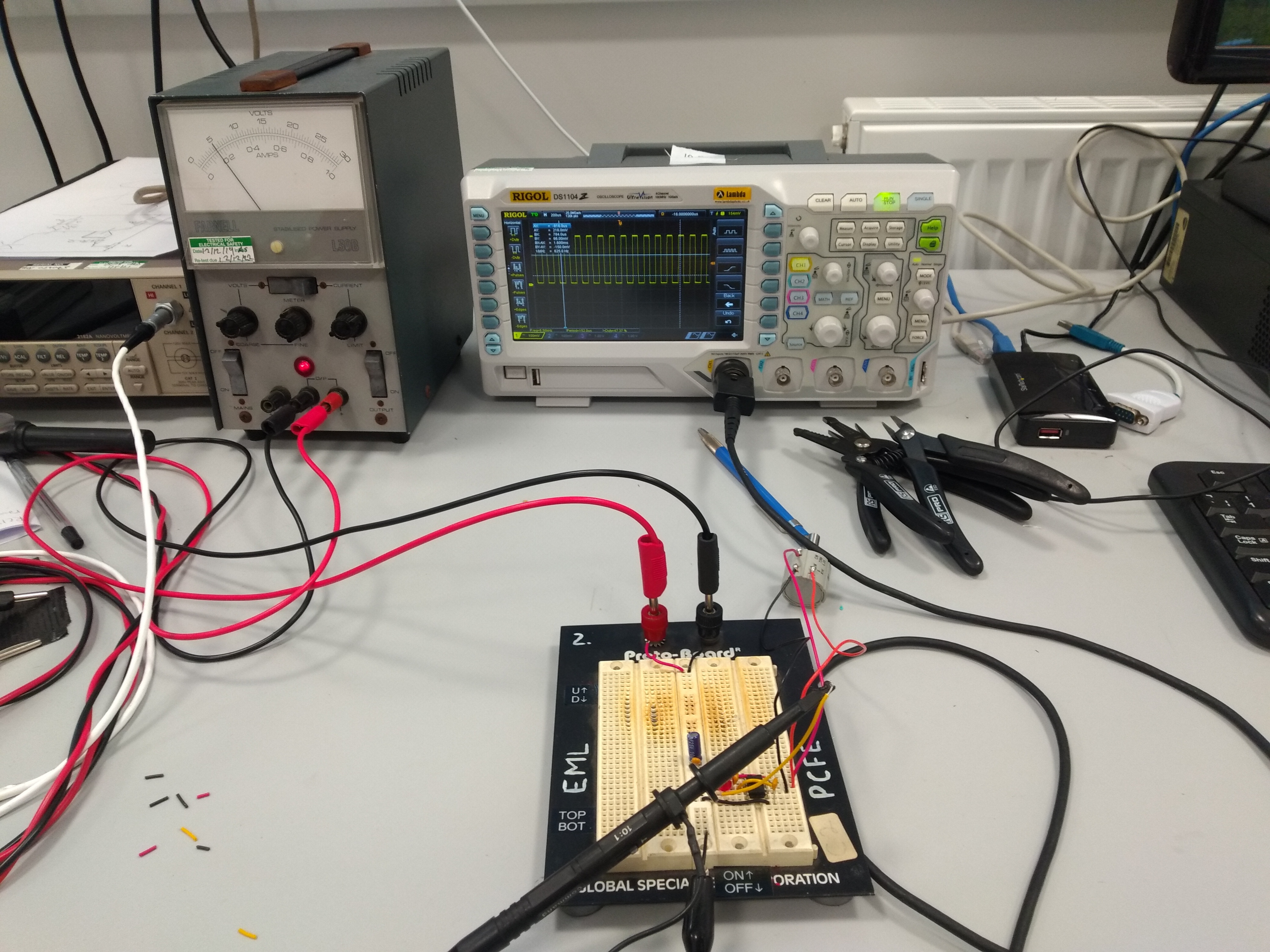
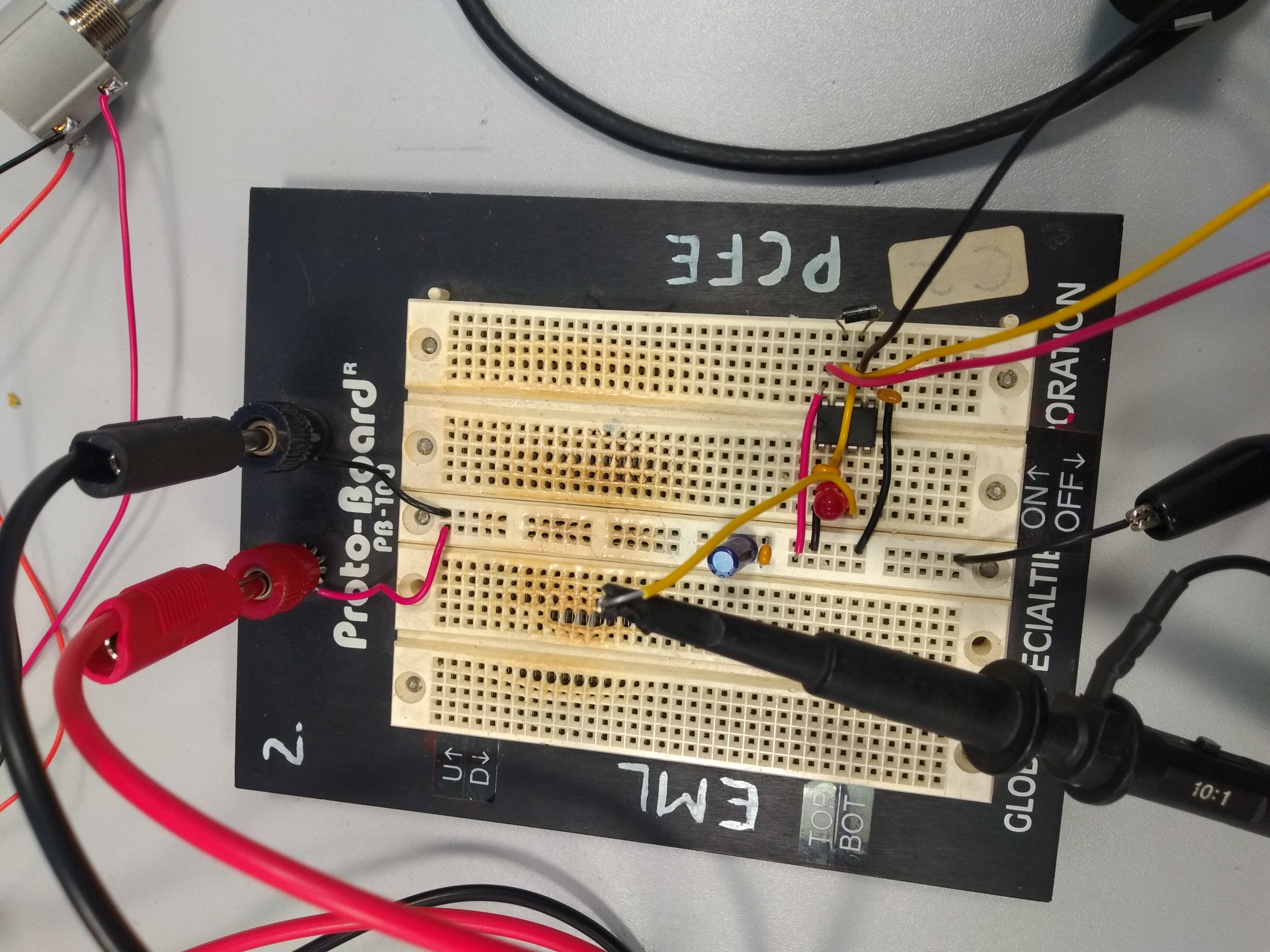
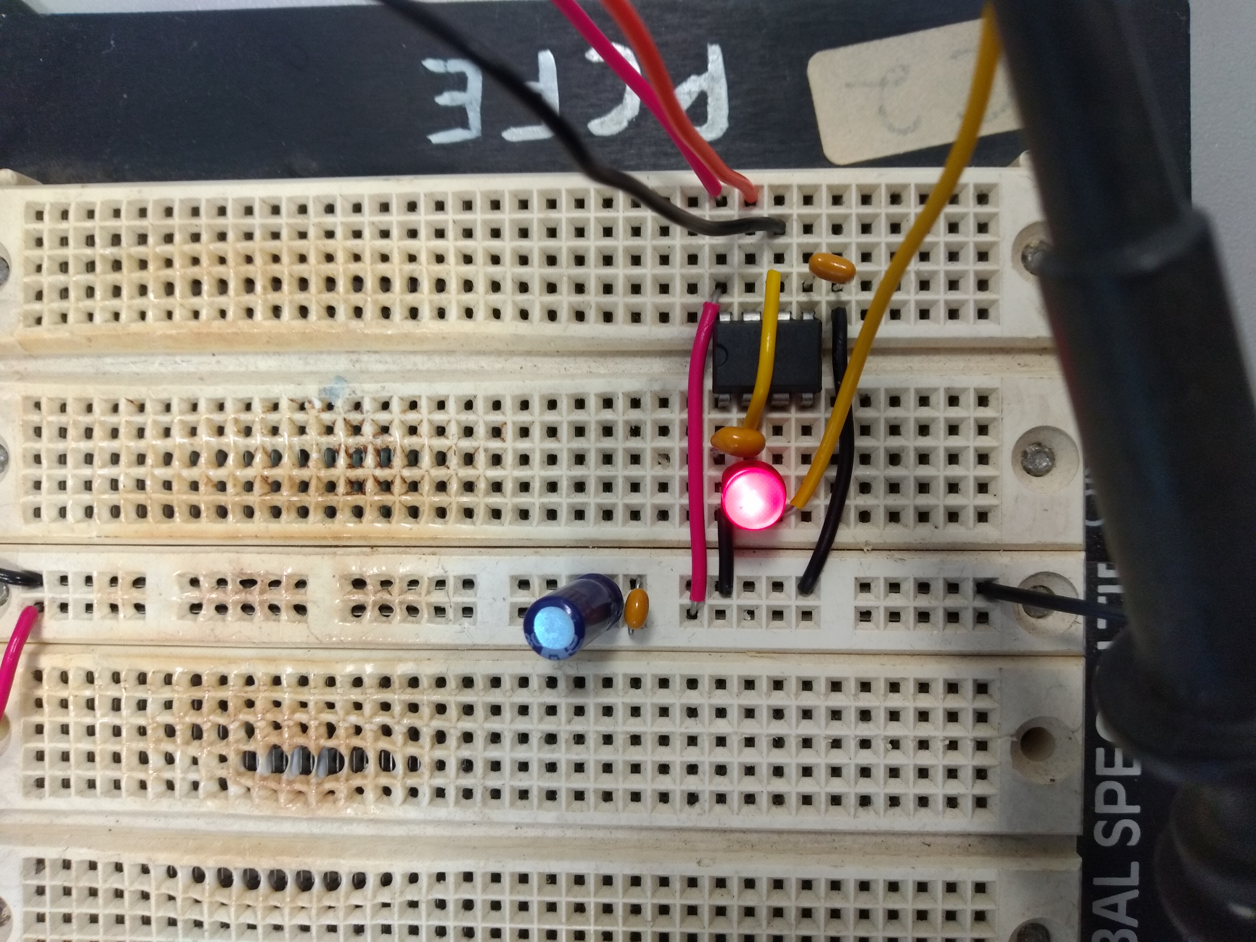
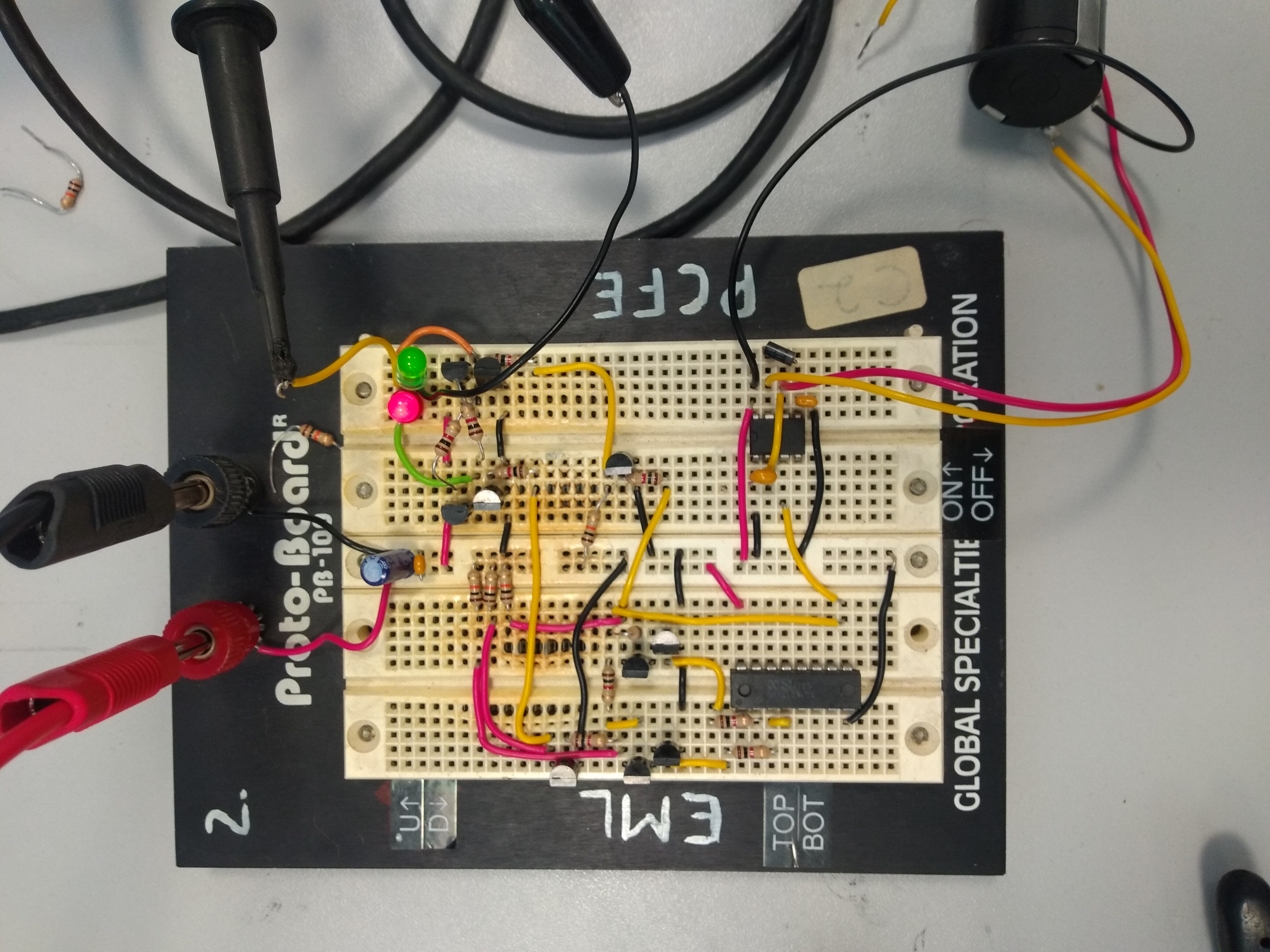
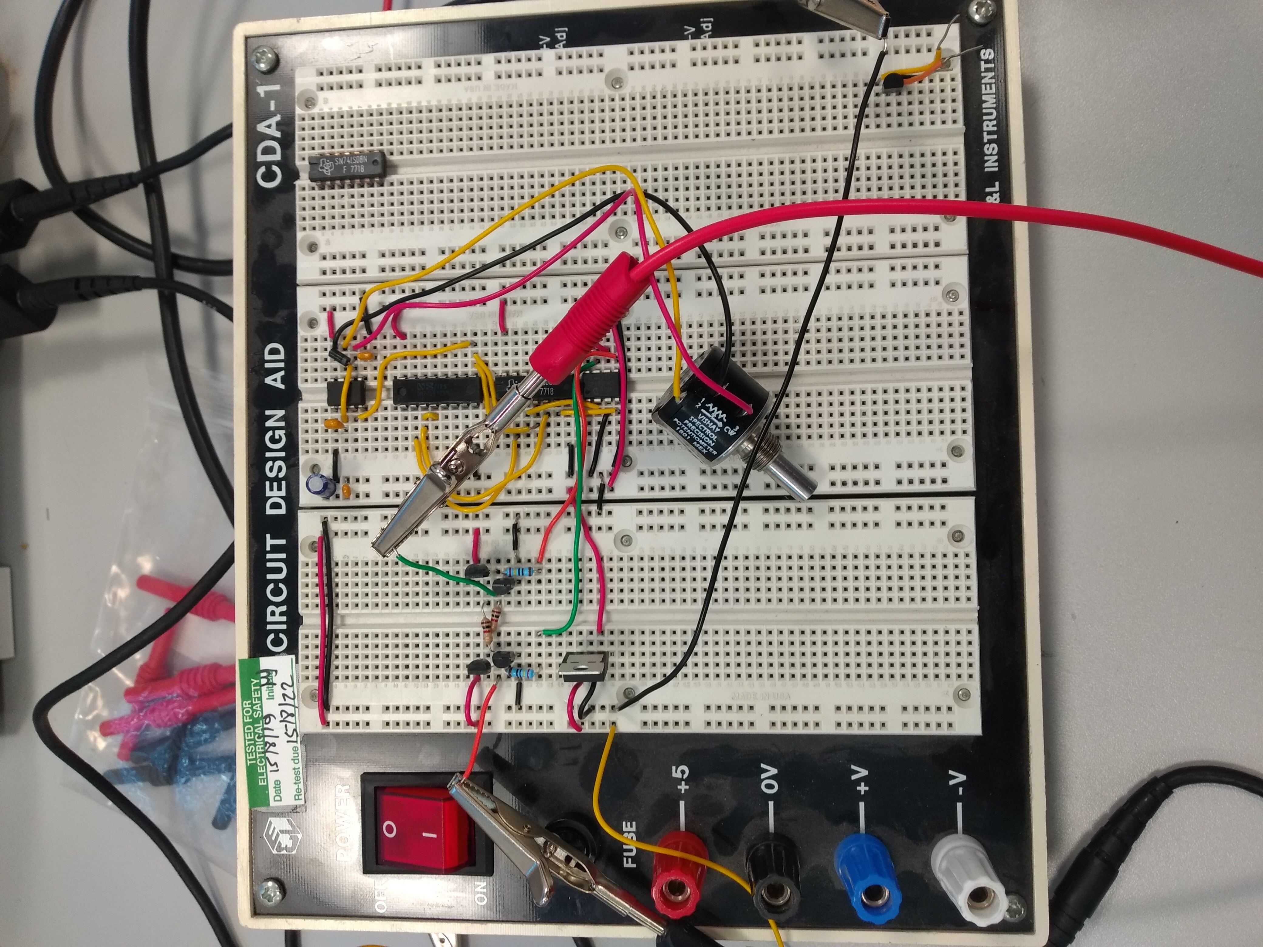
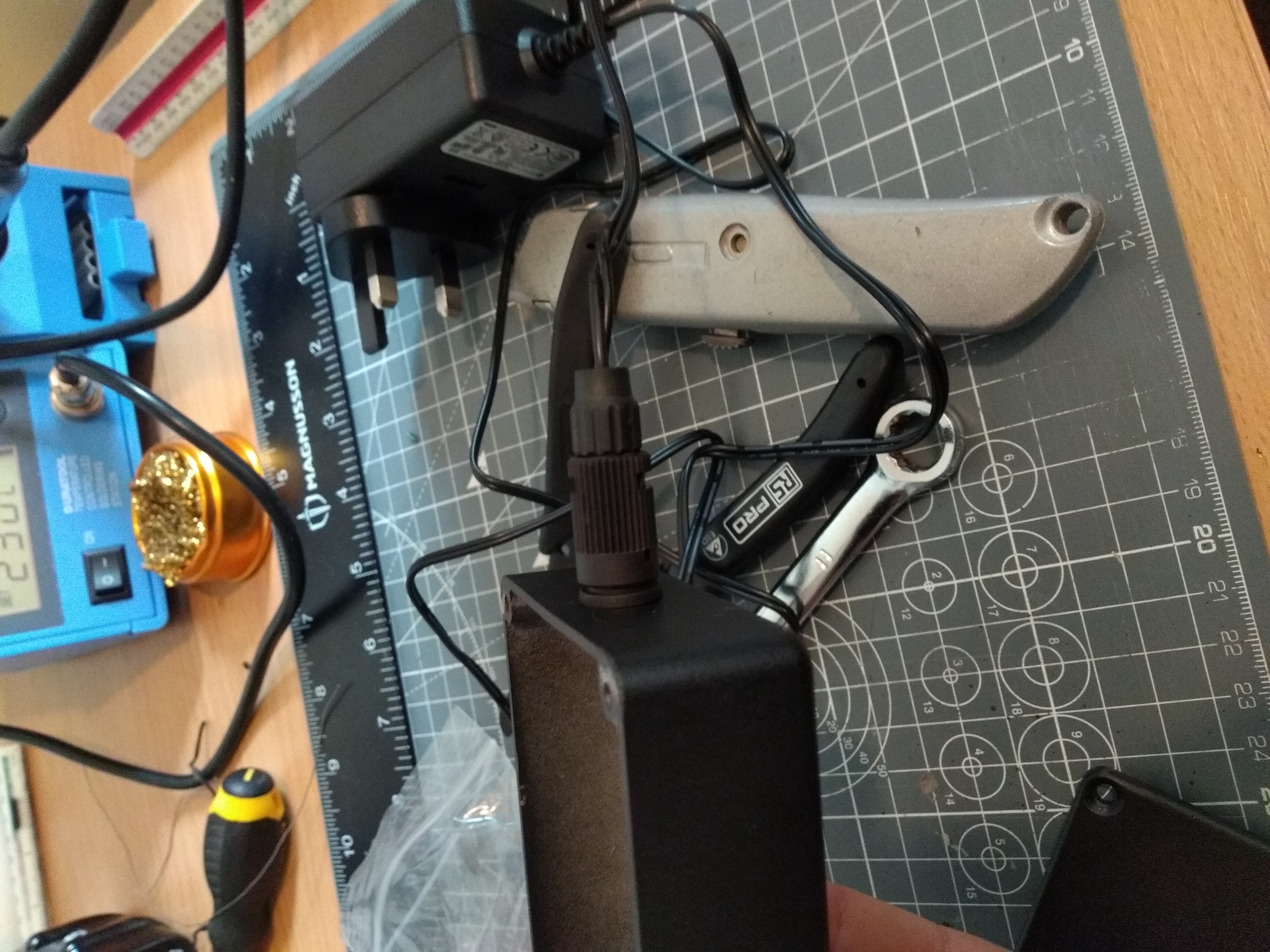
To make the circuit, I first prototyped it on a breadboard. At first I tried to make all the logic with discrete NPN transistors (because I have a very large pile of them) but this became much more difficult than expected and I could not get the circuit to drive (any mistake down the line would blow up a transistor and I'd have no idea what caused it). Therefore I borrowed some DIP versions of the chips used in the SMD version. After a proof of concept was shown to work on a few small LEDs, I hooked it up to the led chain and quickly found that the regulator was searingly hot. I had not realised that the specific version of the and gates I had were only able to source a few milli-amps. This meant that the transistors did not saturate and therefore were highly resistive. I had a 2-channel MOSFET driver IC on hand and decided to use that to source the current. This worked well.
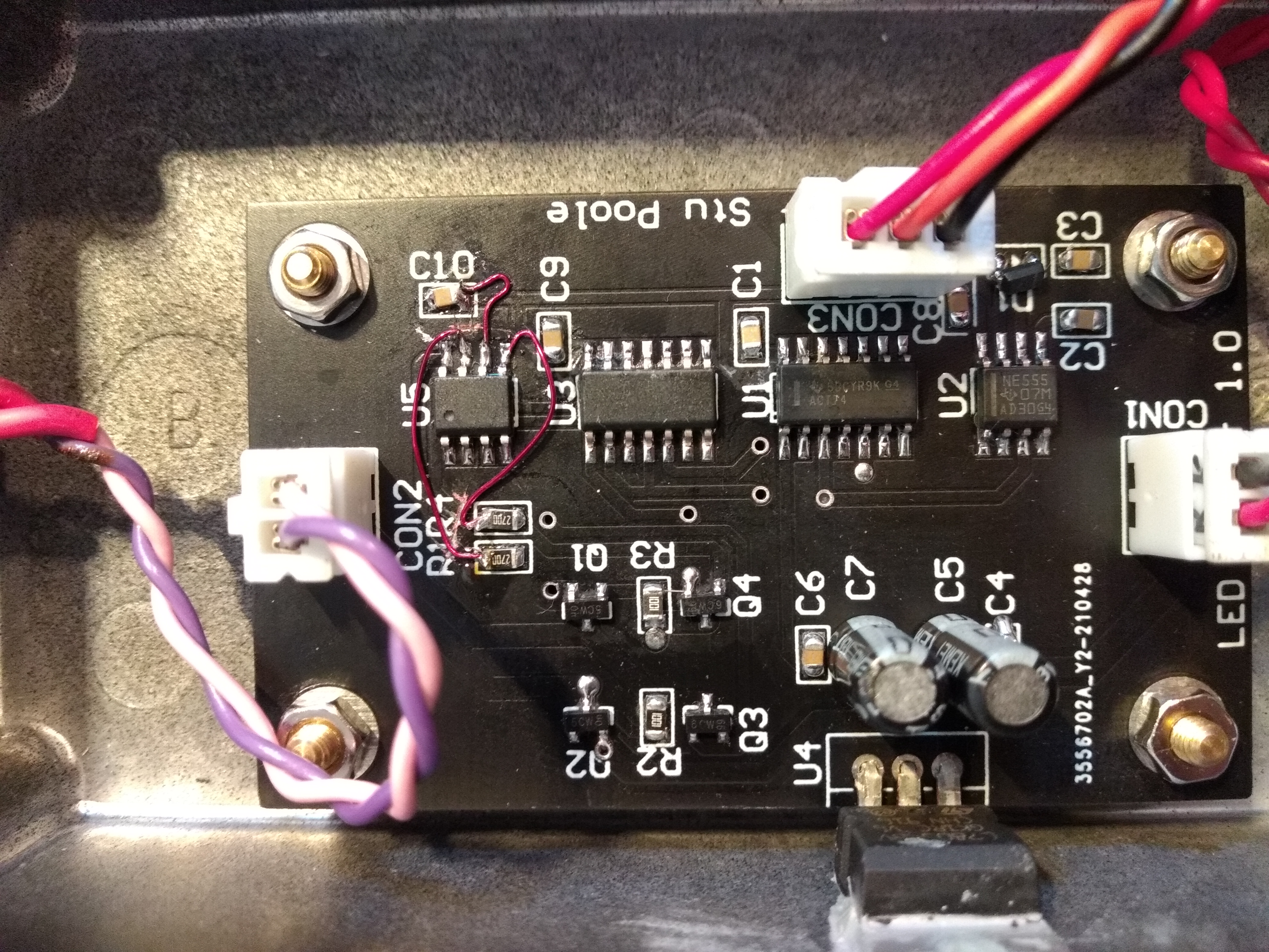
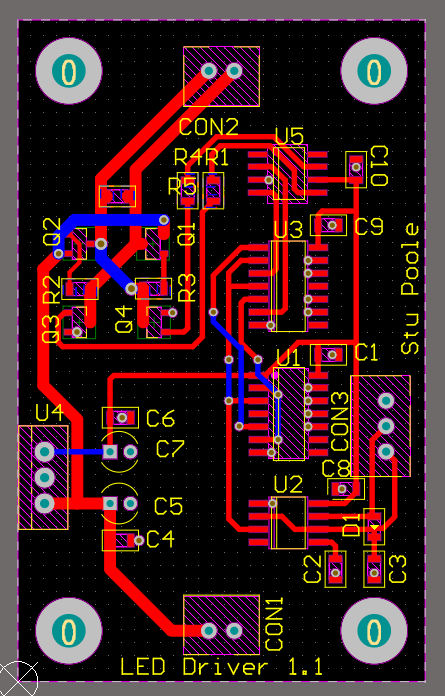
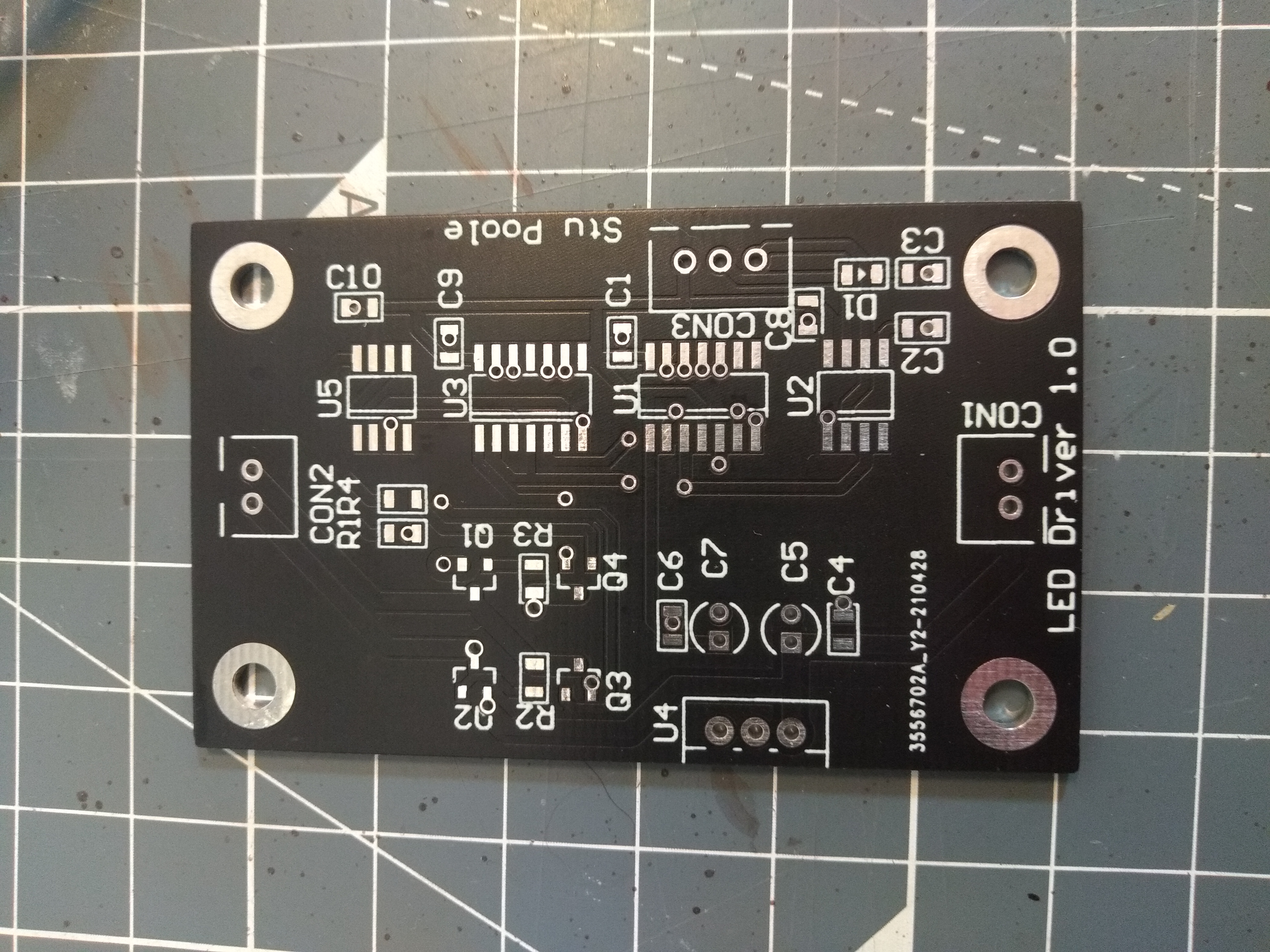
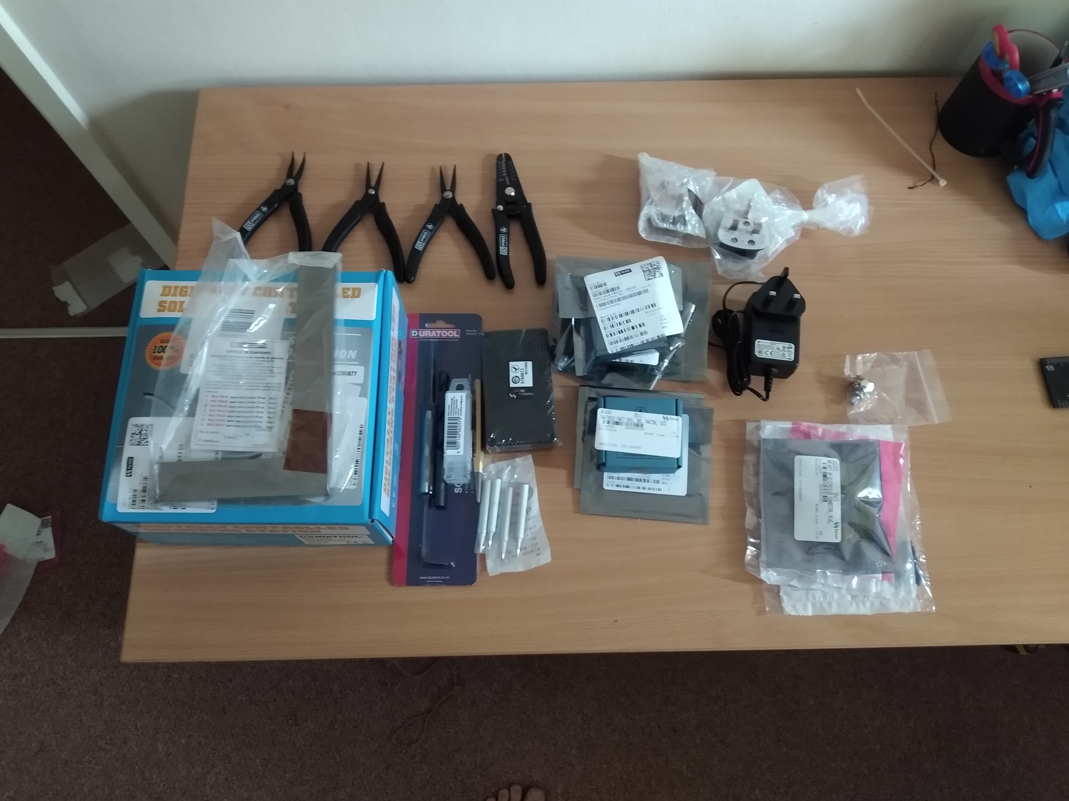
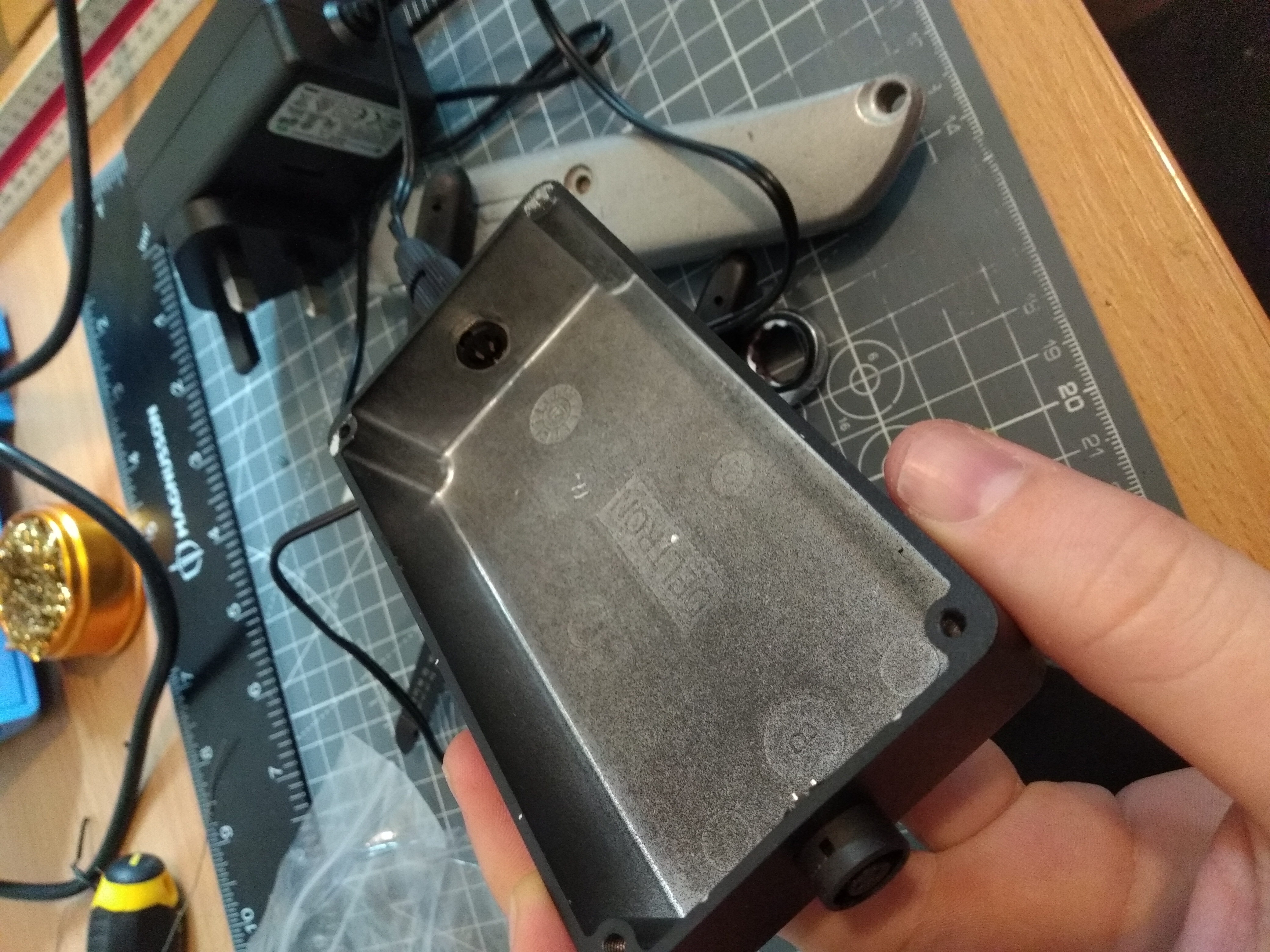
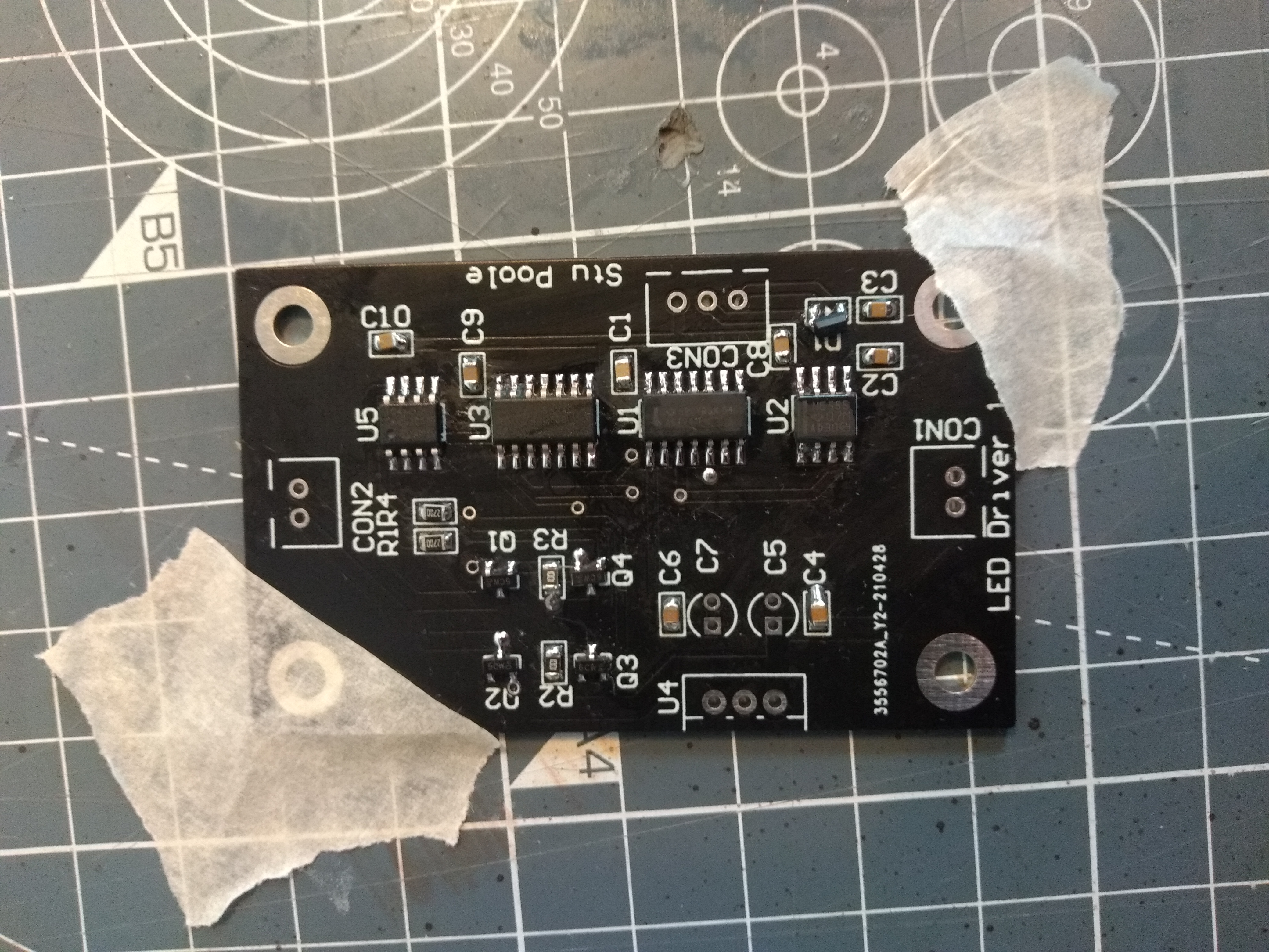
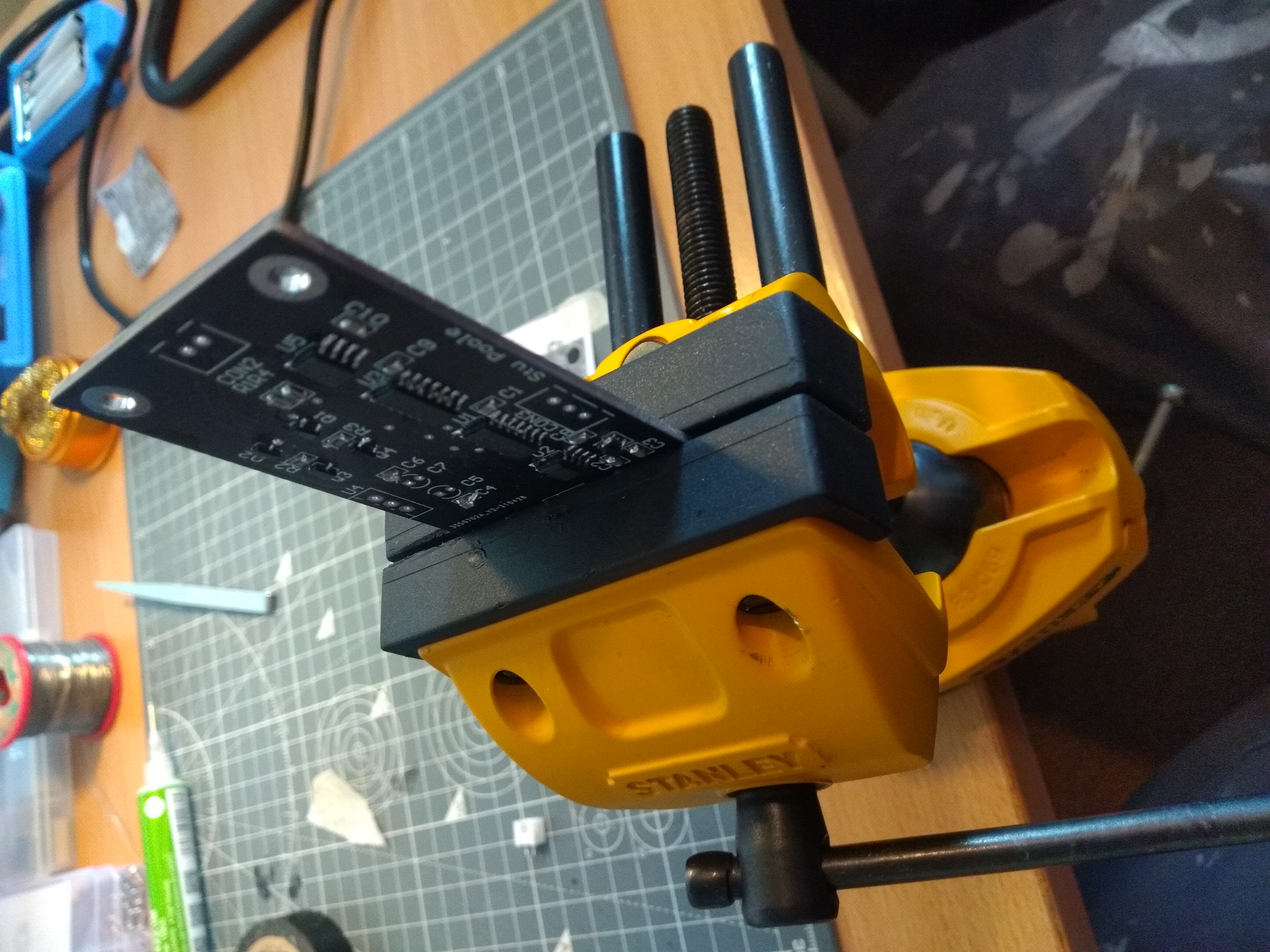
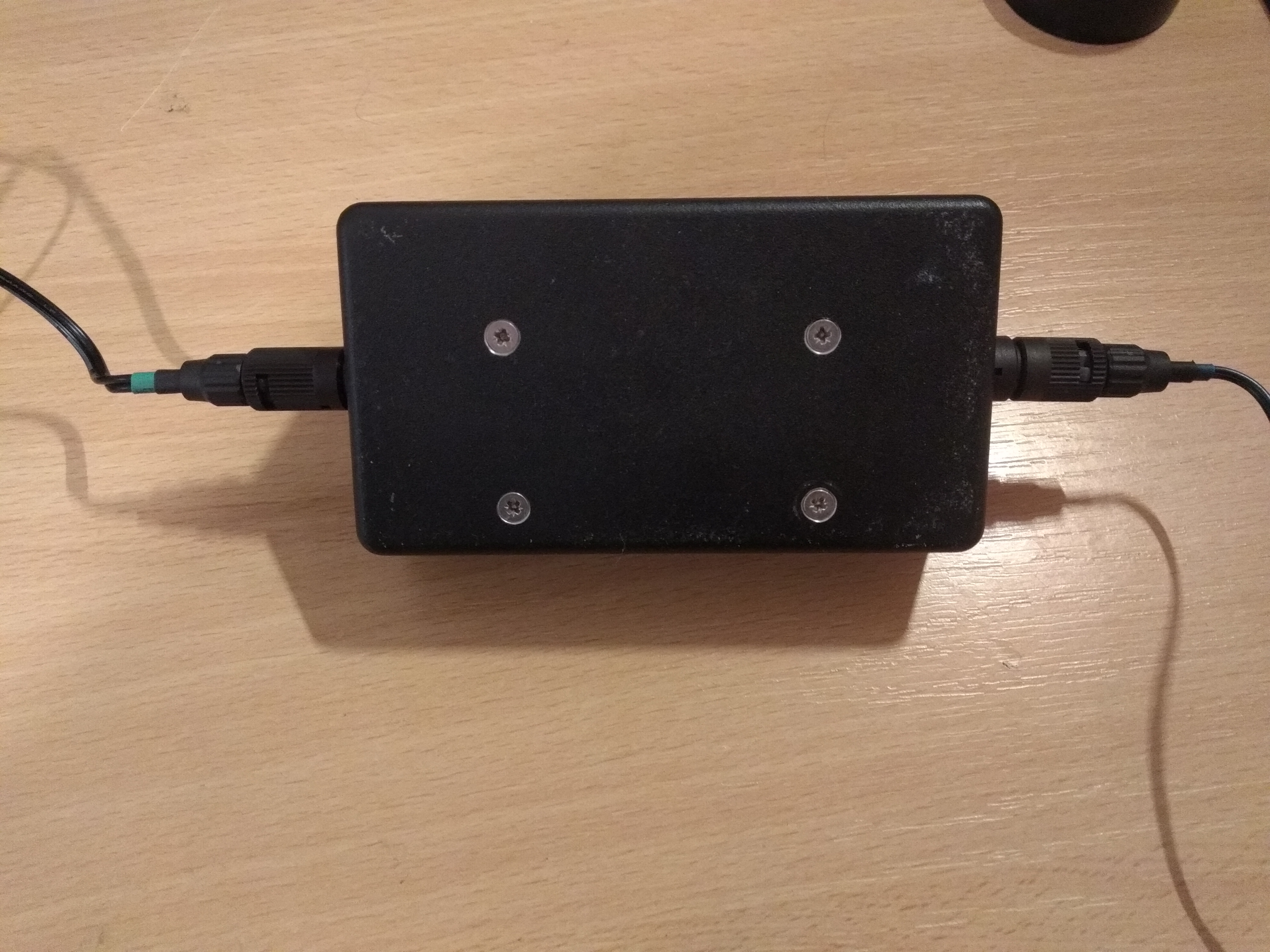
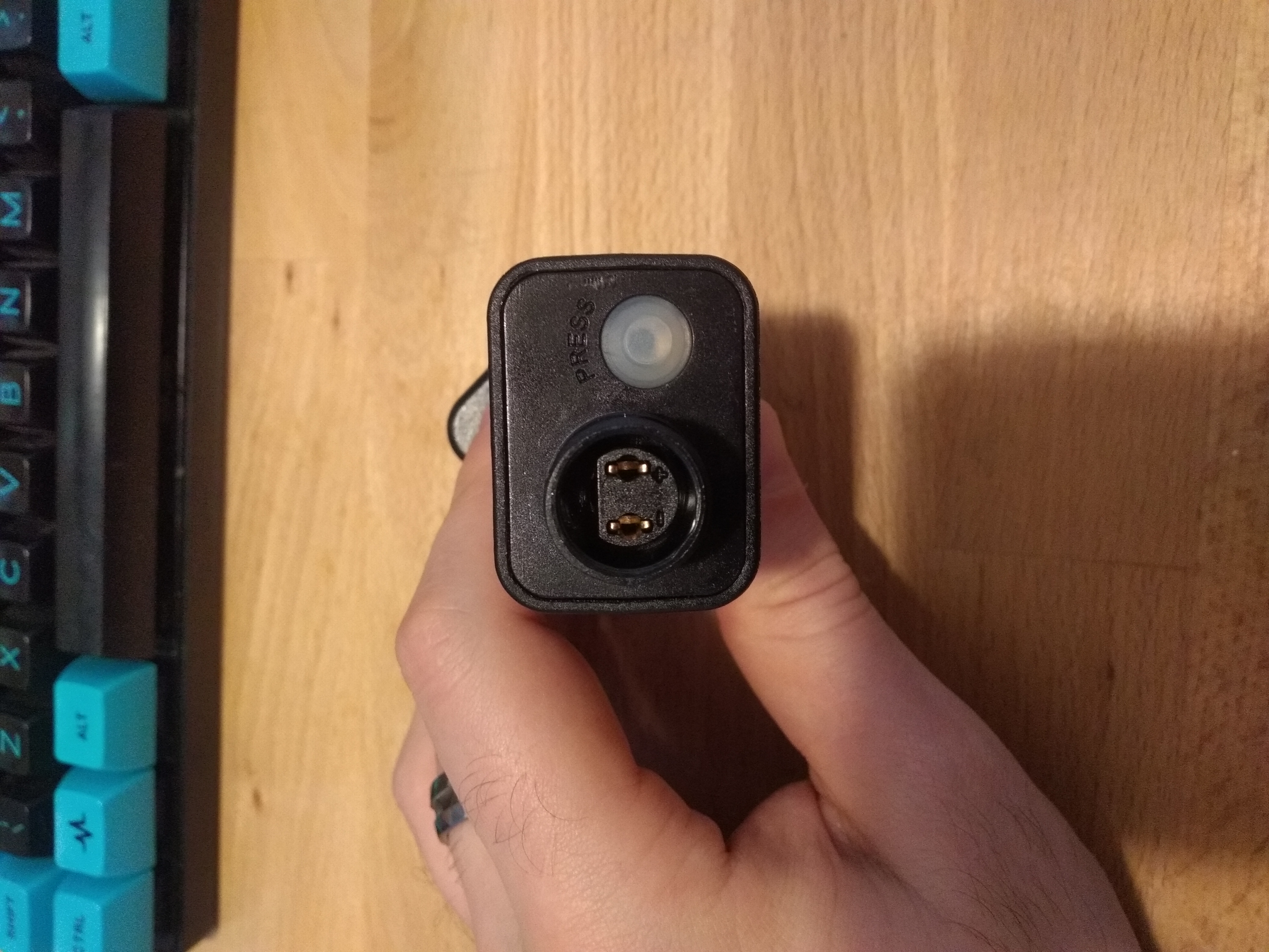
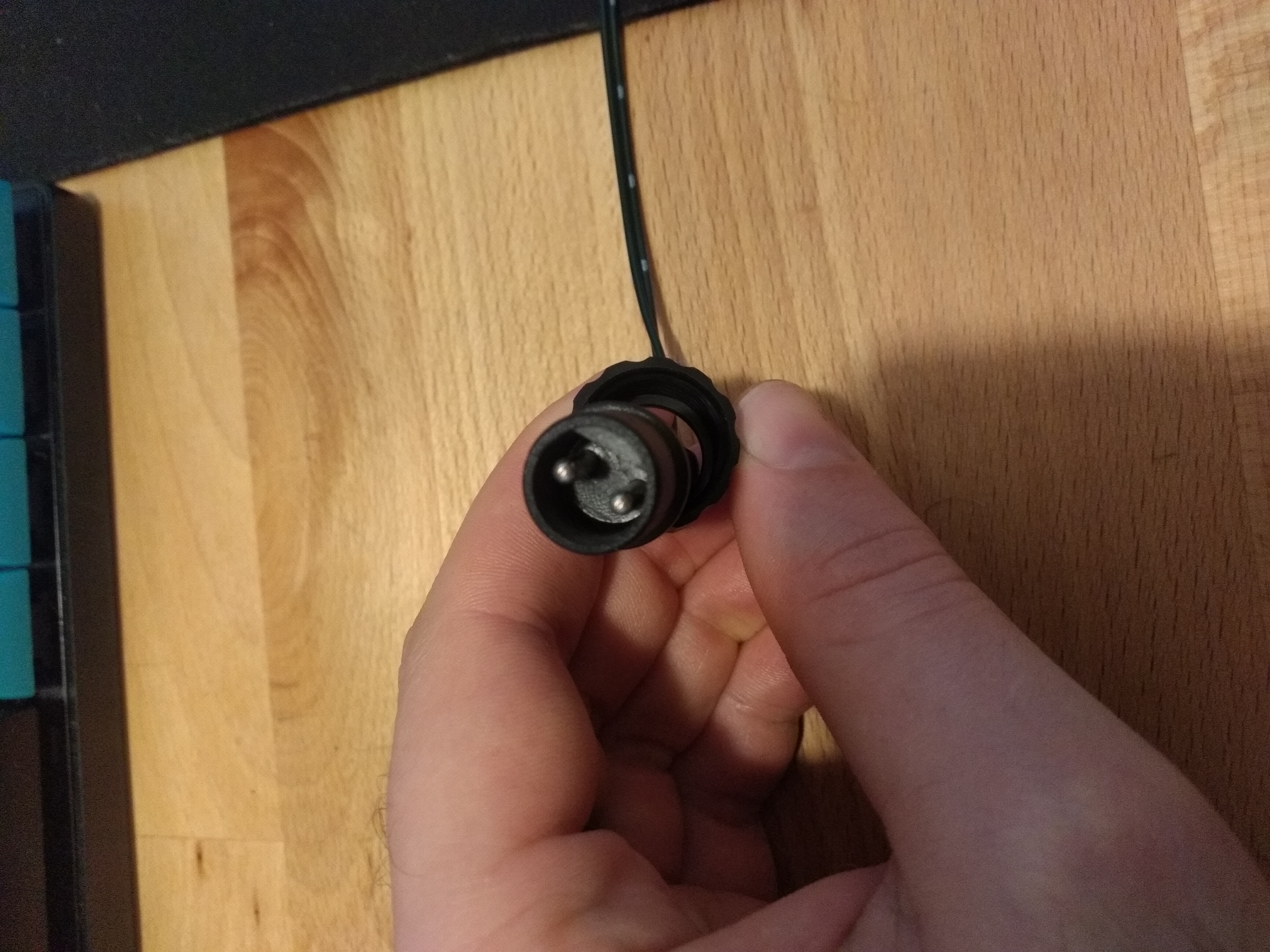
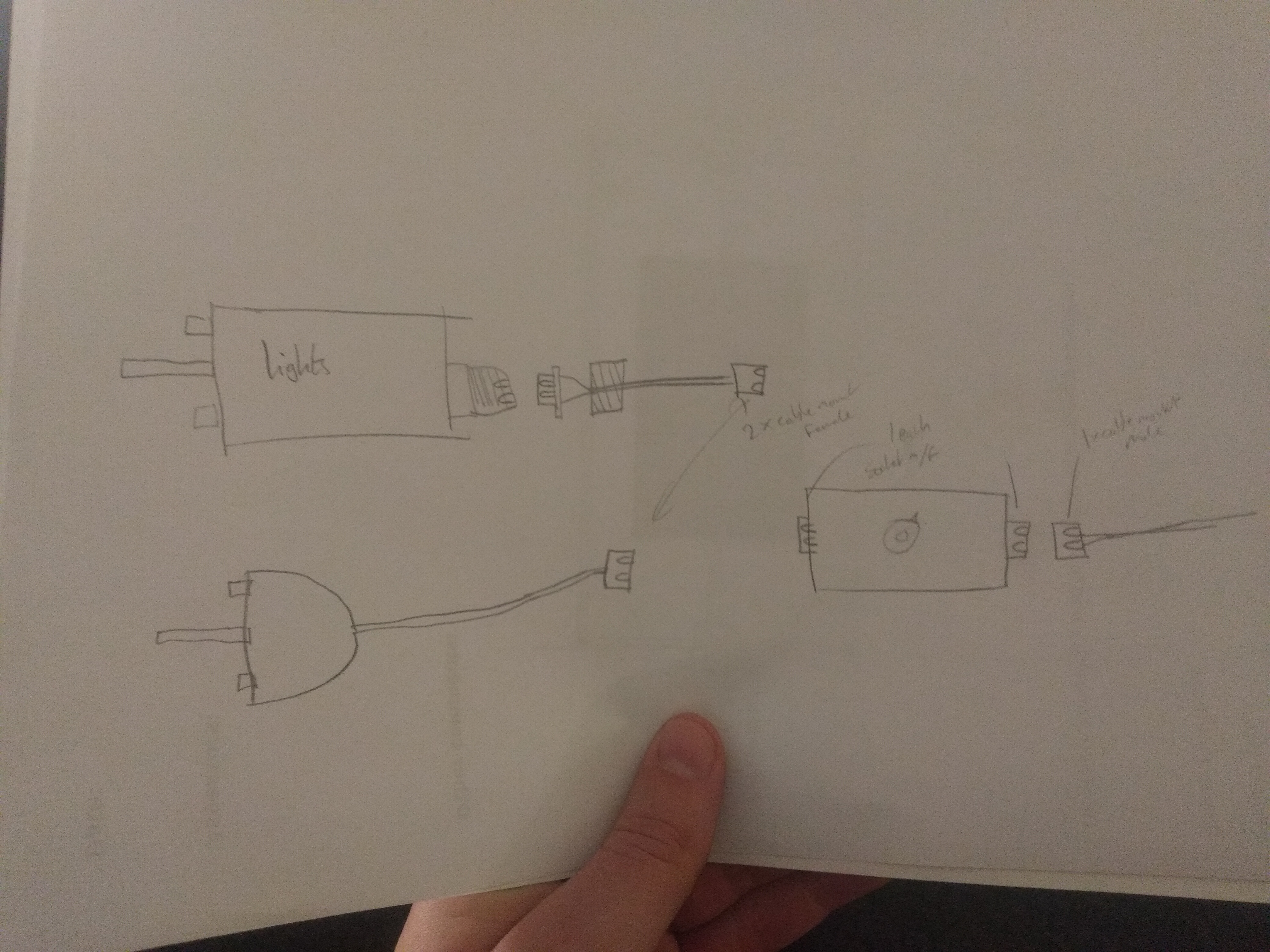
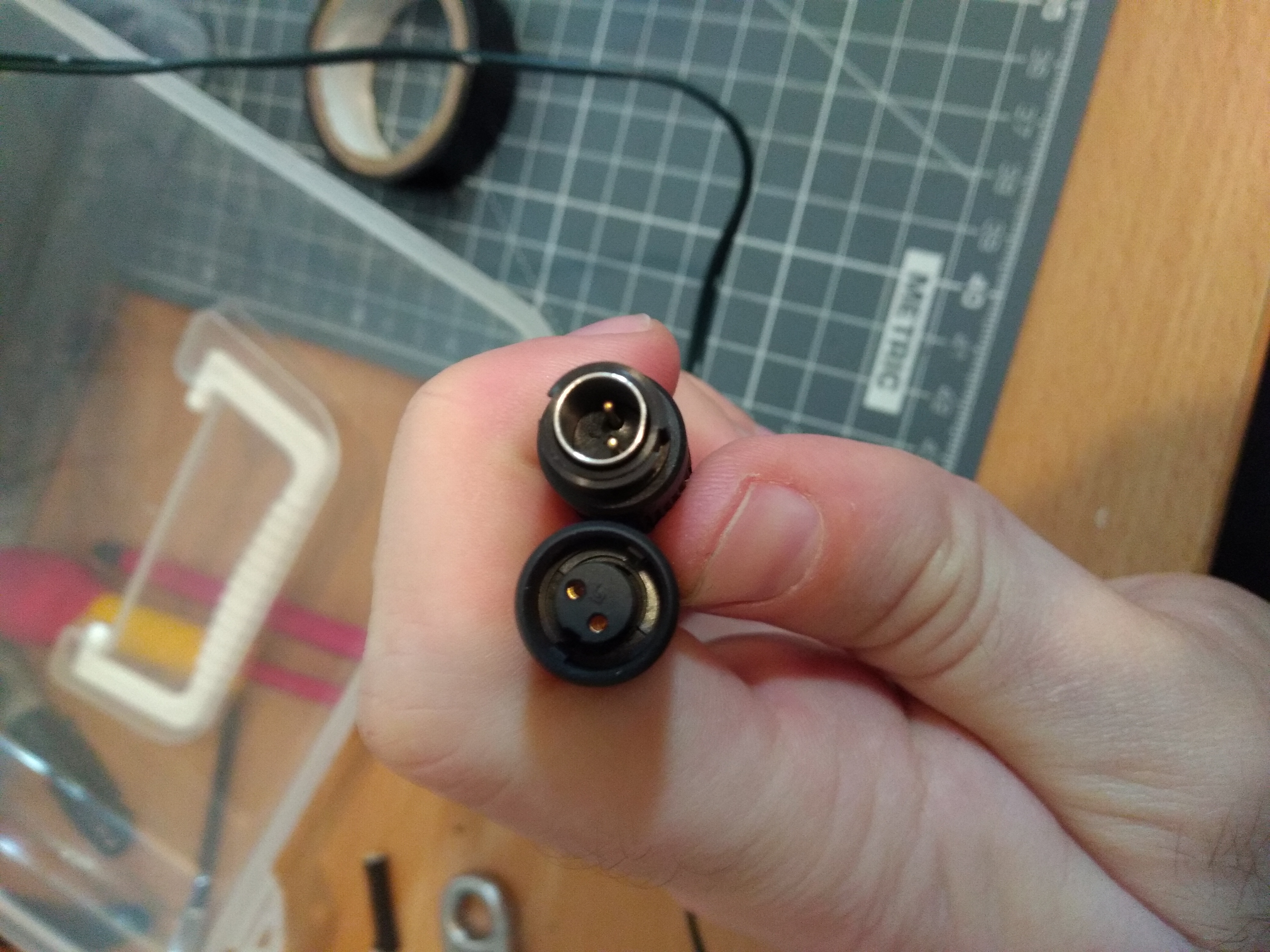
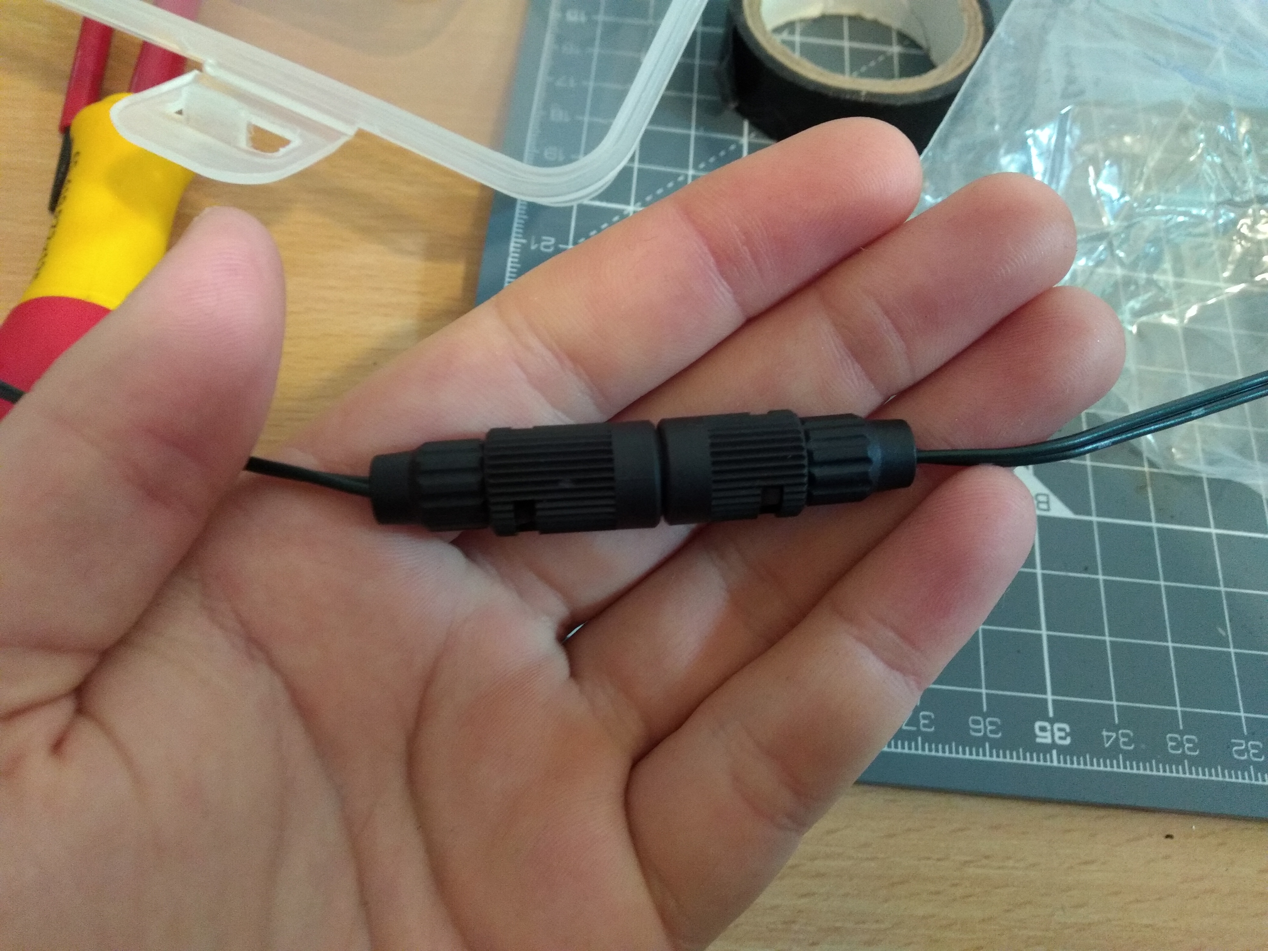
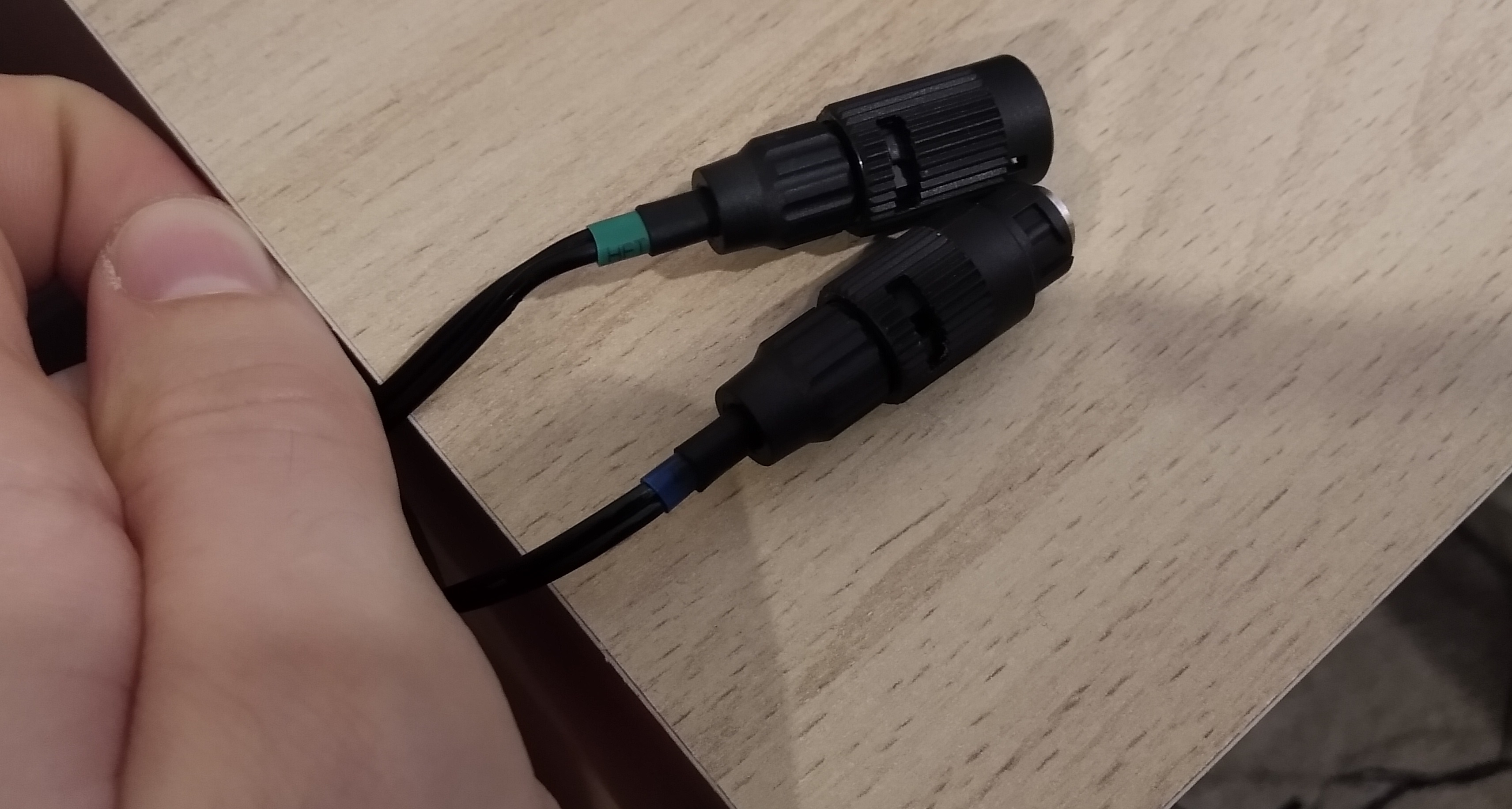
I designed the circuit in Altium Designer 2020, and made all the IC footprints myself, to make sure they were uniform. I only made one mistake in this process, and labelled the LED diver's right hand side legs wrong (1,2,3,4,8,7,6,5 instead of 1,2,3,4,5,6,7,8 in CCW direction). This is fixed in the downloads below. I ordered 0805 diodes on ebay and received a different family of package entirely. I managed to bend the leads and solder it on sideways but was very annoyed. The regulator did not fit under the lid and so the top was cut off. In hindsight, I could have added leads and mounted it anywhere else in the box. These were the only botches on the board, three neat bodge wires, trimmed regulator and a sideways diode. JST connectors were used throughout and, apart from the cheap potentiometer, the parts are all name-brand. To make the connections, mini circular connectors were used, all with a satisfying click. It is not possible to incorrectly connect the lights to the input or the PSU to the output but it is possible to connect the original PSU to the input pins of my box and that could be catastrophic for my circuit without polarity protection.
The potentiometer I chose has a built-in SPST switch which would normally be fine but for these LEDs, the AC pickup from the wiring in the house causes the lamps to glow very slightly, only visible in very dark conditions. In a future revision I would add polarity protection on the input. I have spent many hours searching for a DPDT or SPDT switch with the same form factor but the one I could find was discontinued in 2019 or 2020. There is one company (from my hometown, as it happens) producing a good solution, but I cannot find the exact one I need for sale in the UK. Ideally the potentiometer would be logarithmic to get more control in the dim regions.
Overall, the driver circuit works well and my first ever SMD soldering came out very well. There were a few teething issues, as is common with prototypes. With these ironed out, I believe I would have made something quite good, although altogether unnecessary!
Crokinole Board
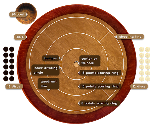
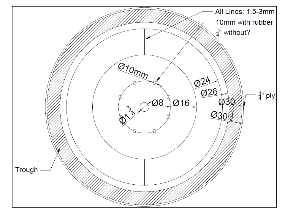
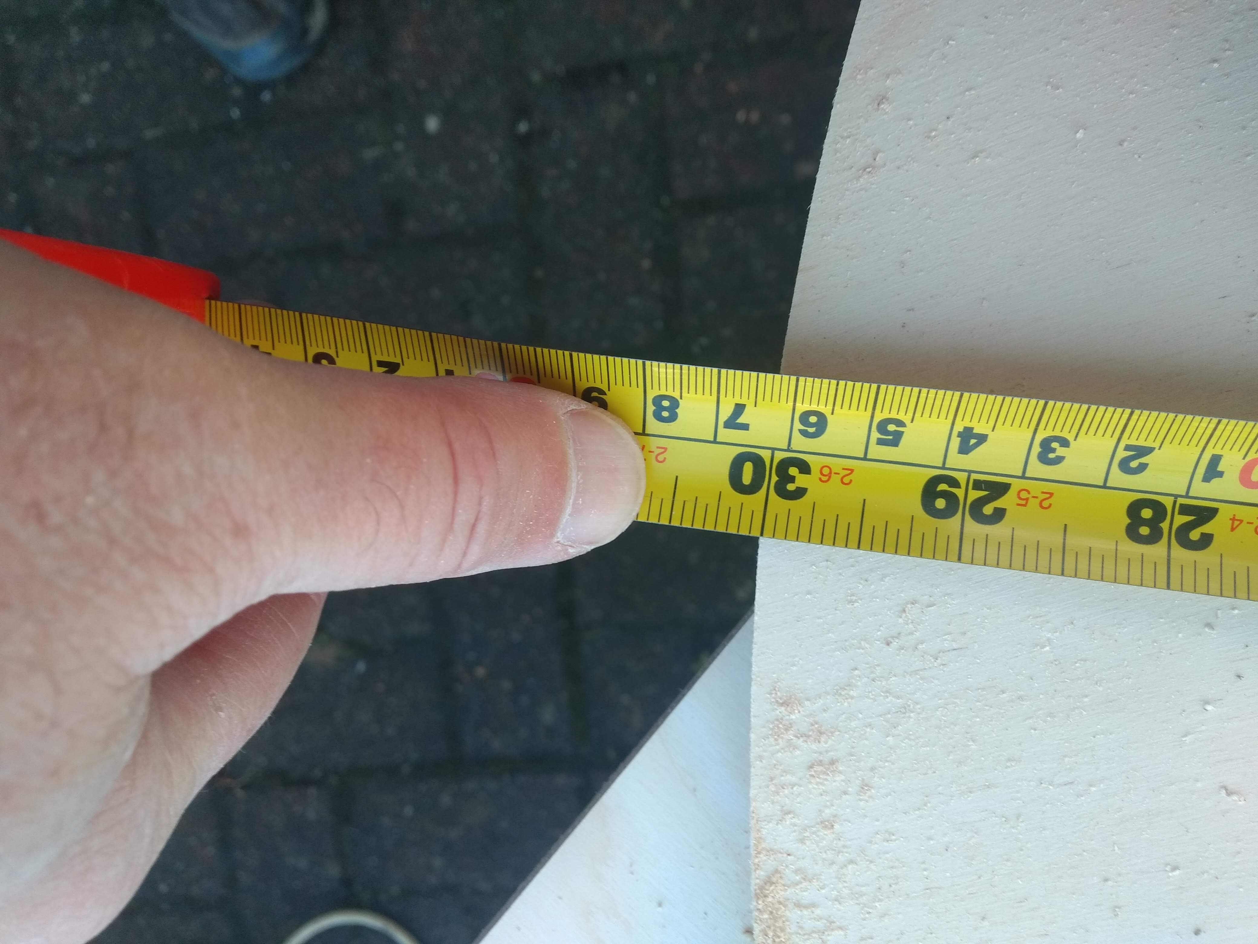
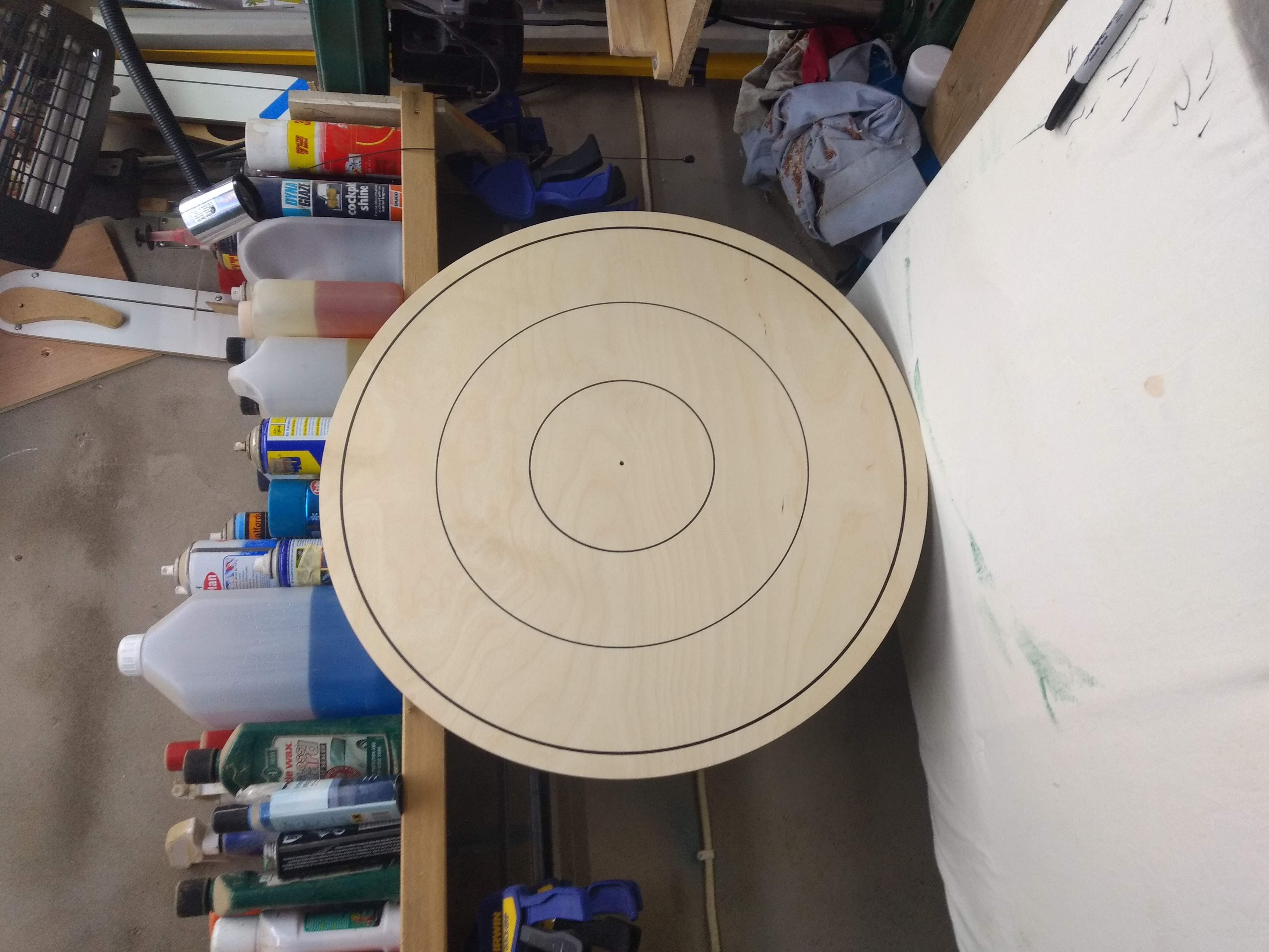
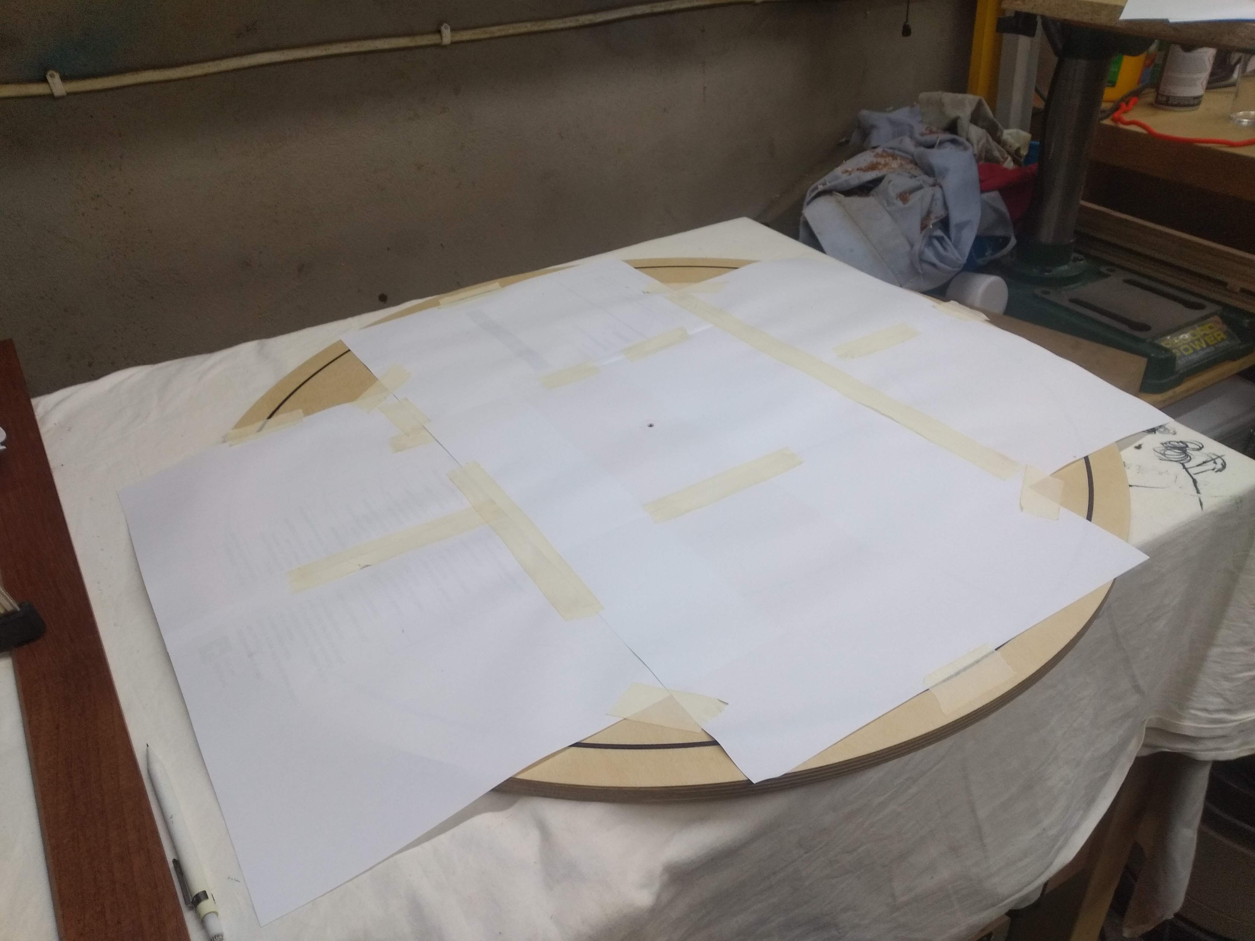
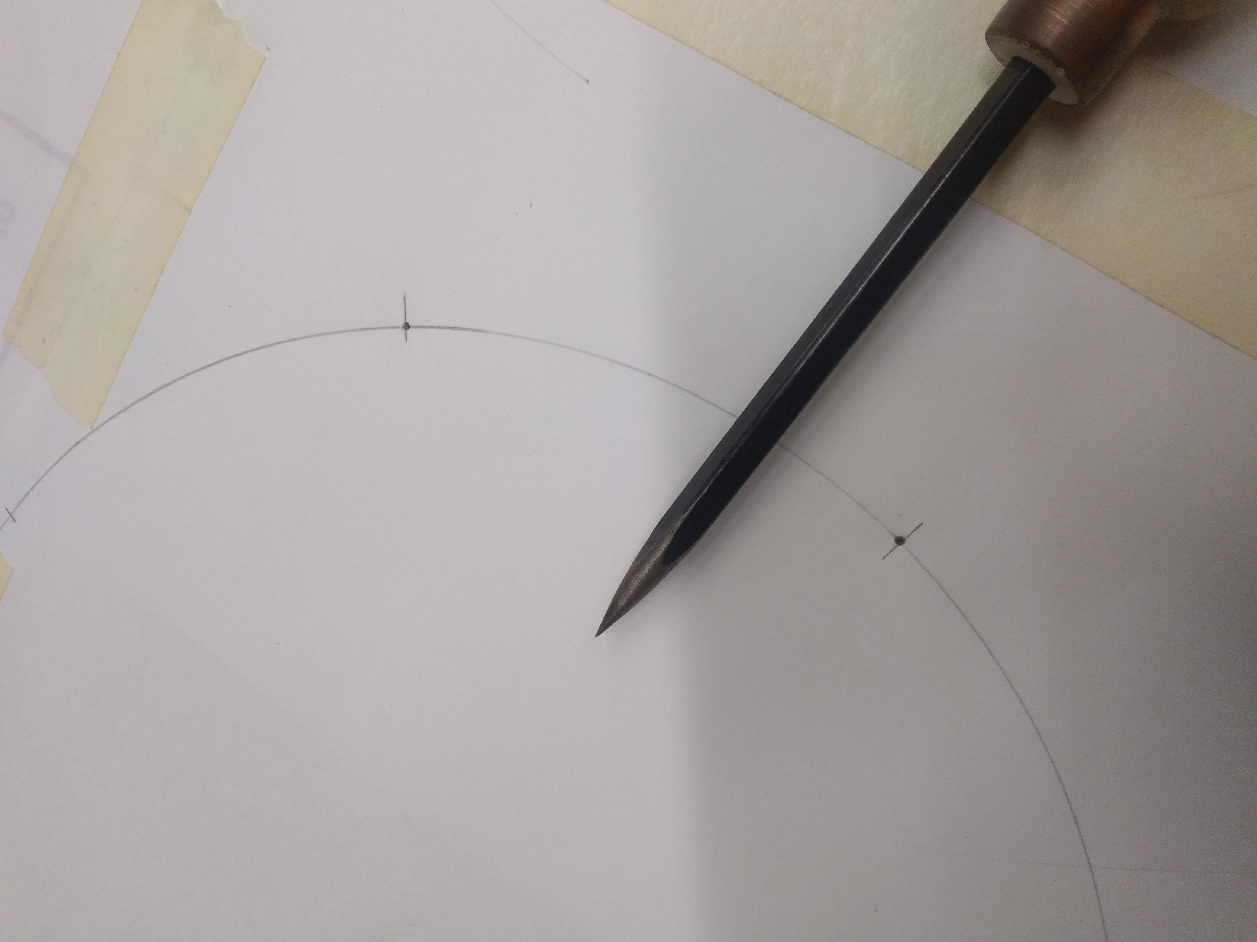
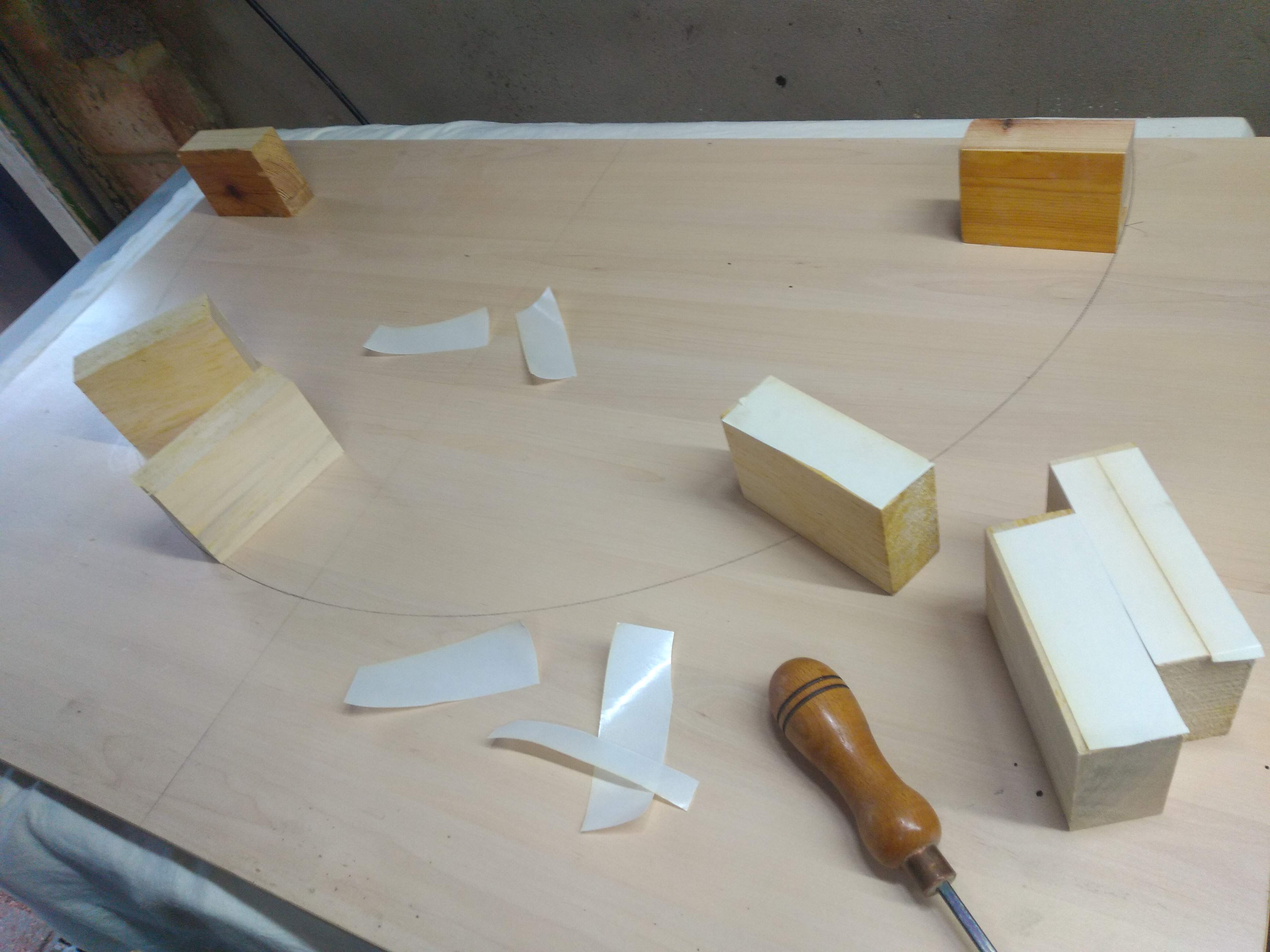
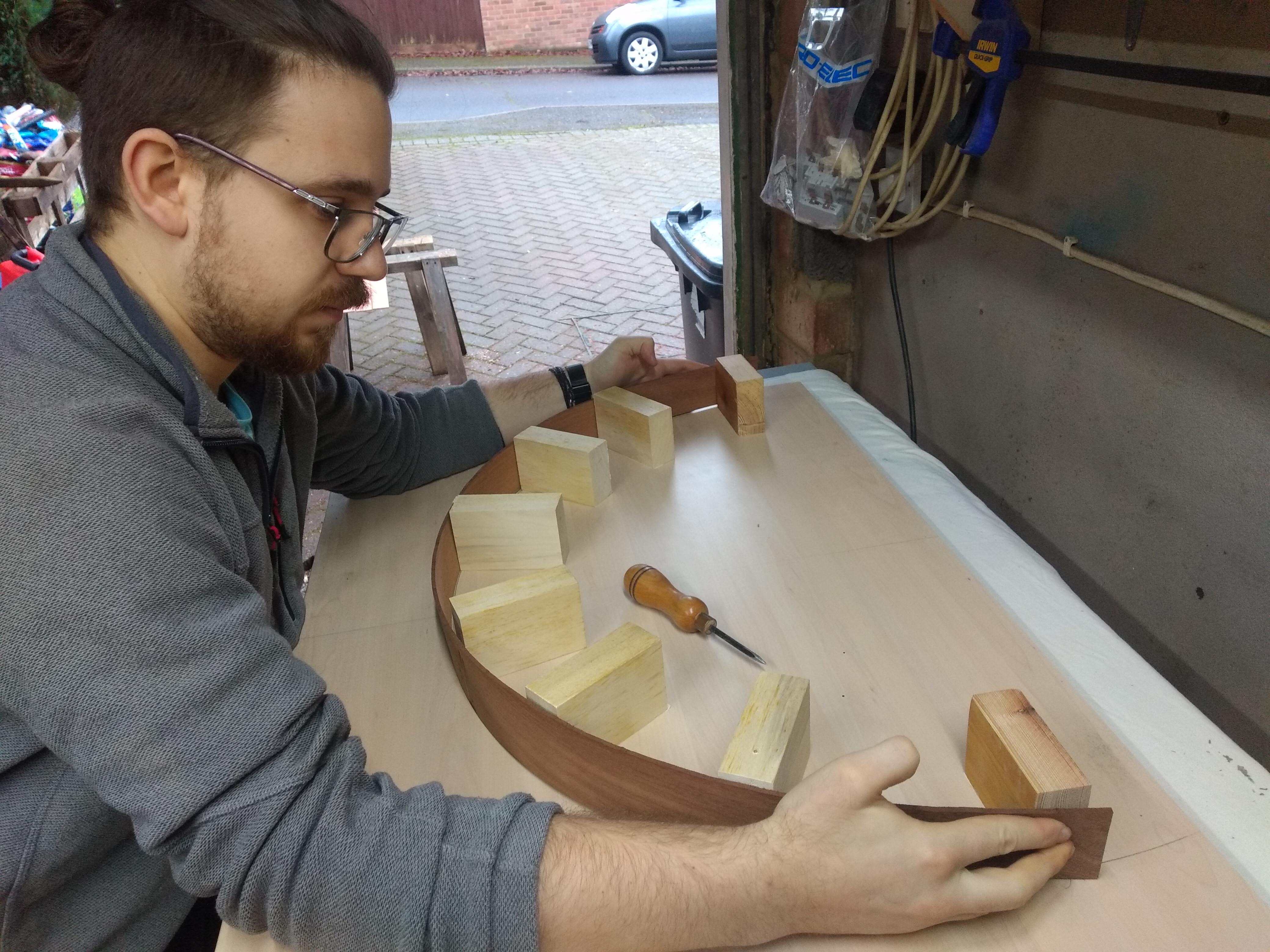
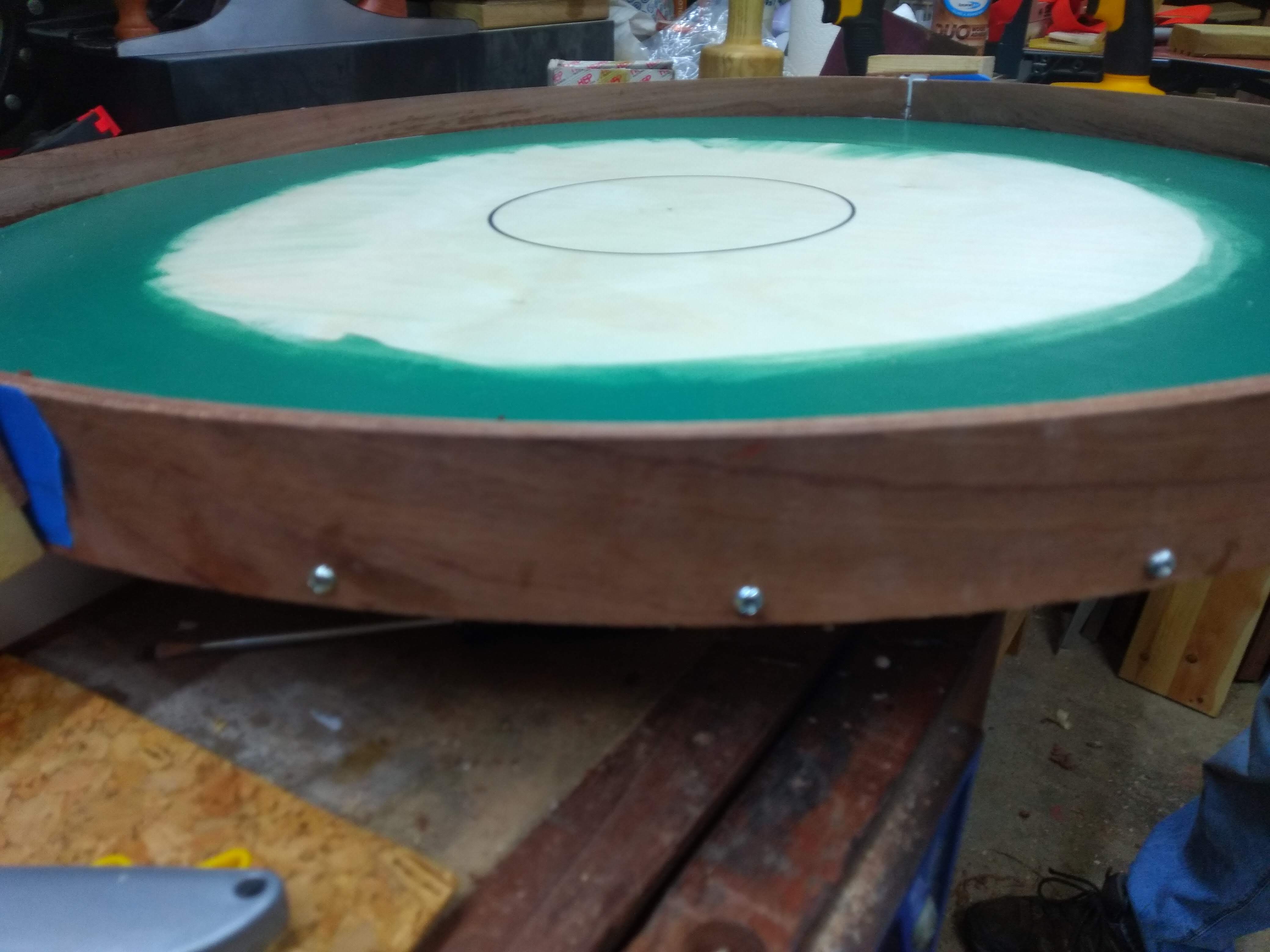
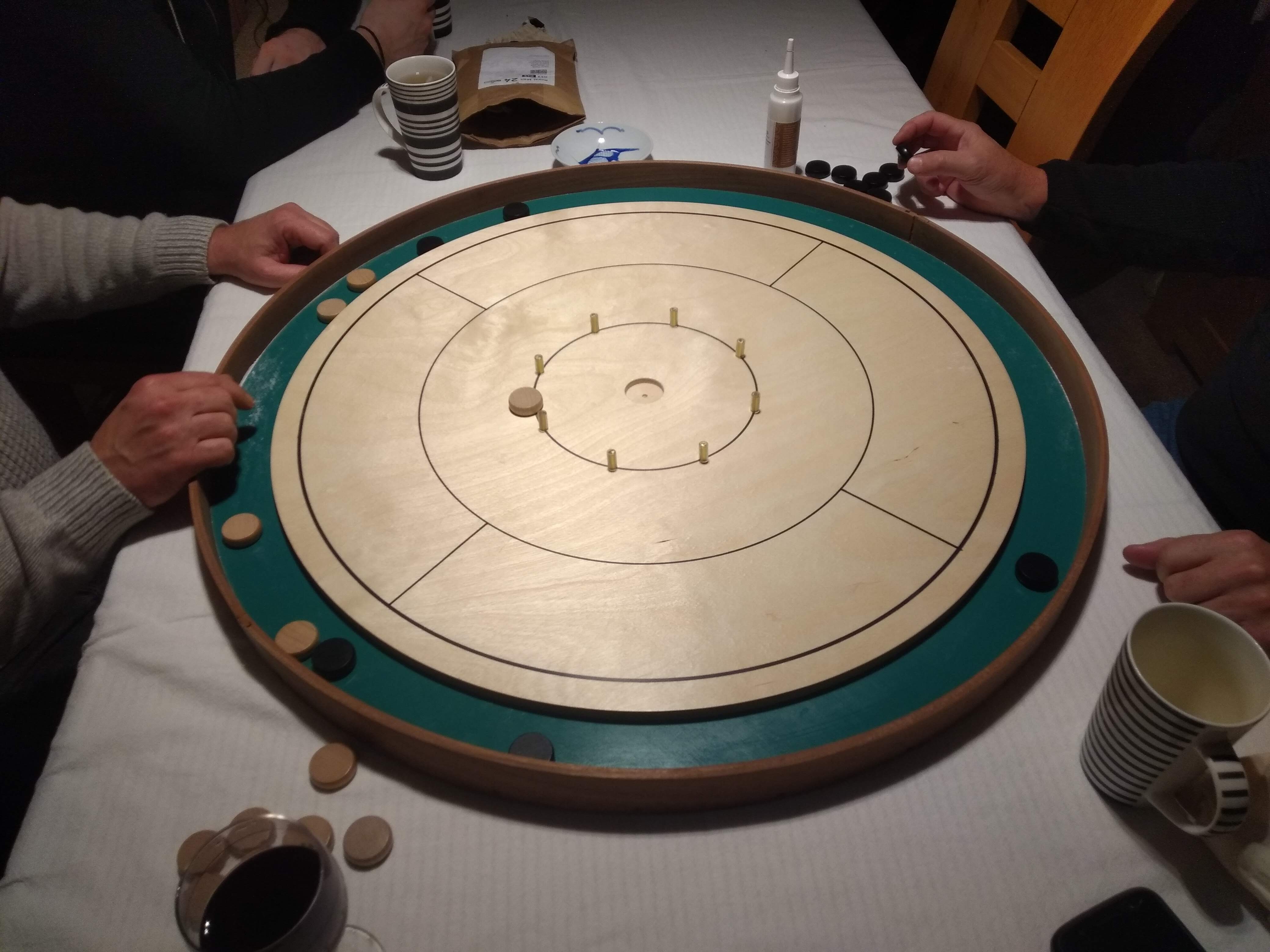
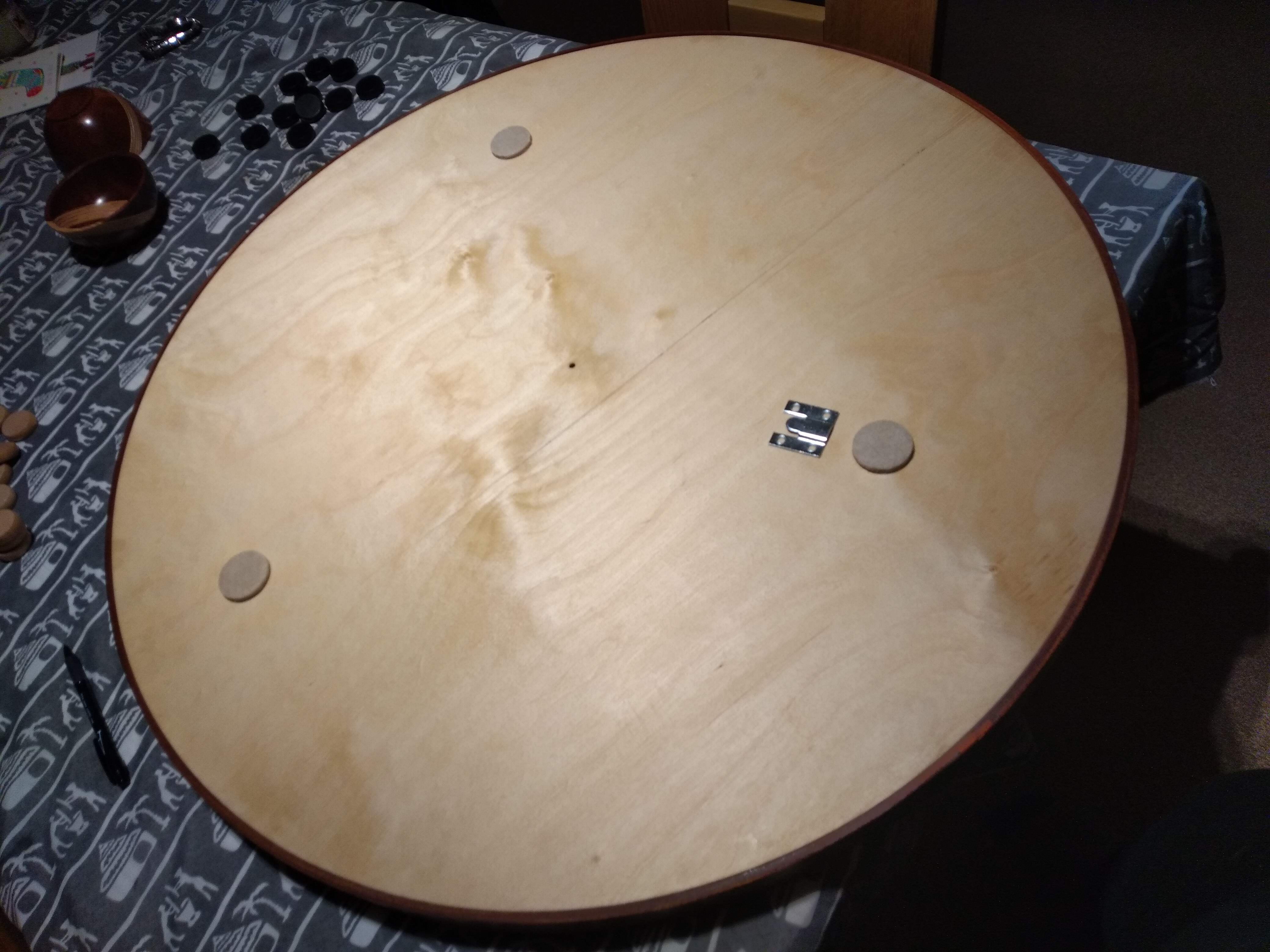
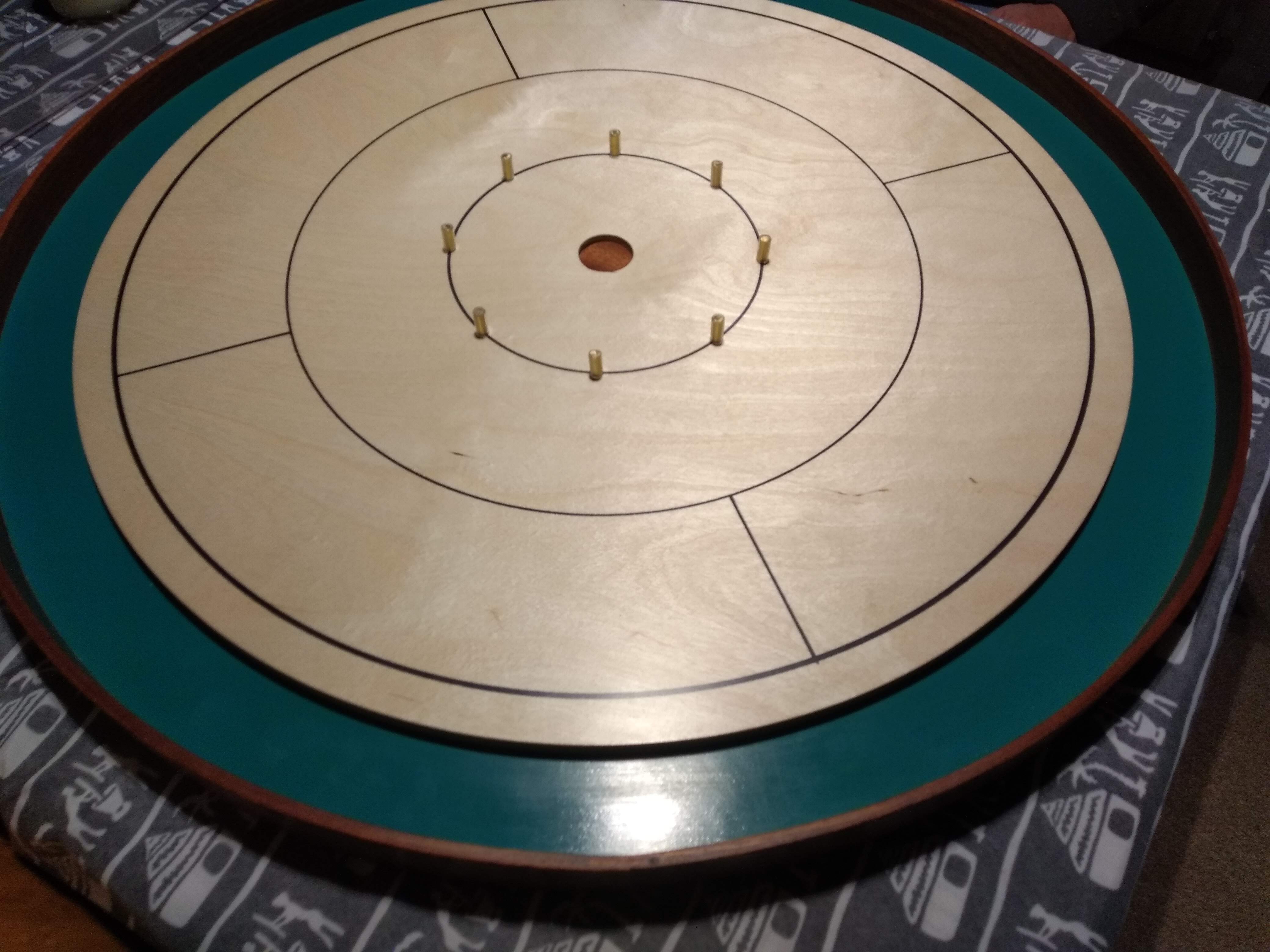
Board games are great, and modern board games are awesome, but they have some major drawbacks. Finding people who are committed enough to learn a complicated (and therefore rewarding) board game can prove difficult, and teaching it even more so. That's why the most popular board games (apart from chess) are so simple; that's their appeal. Crokinole appears to be both incredibly rewarding, simple to teach and quick to play. I have wanted to get a Crokinole board since watching this video in 2019. A Crokinole board, however, is definitely not cheap and is very awkward to store. I was hoping to make one to play with family over Christmas and so I drew the tournament specifications for the board in CAD and made a model to work from. Not drawn are the thicknesses of the boards. It is typical that the board is 1/2" thick and sits on a base of a similar thickness. The rim should sit 3/8" above the playing surface as should the pins. The centre hole should be roughly 1/4" deep (5 or 6mm are also suggested). The pins should be about 10mm but this size is not clearly specified. Now that I had a plan, I had to get to work persuading my dad!
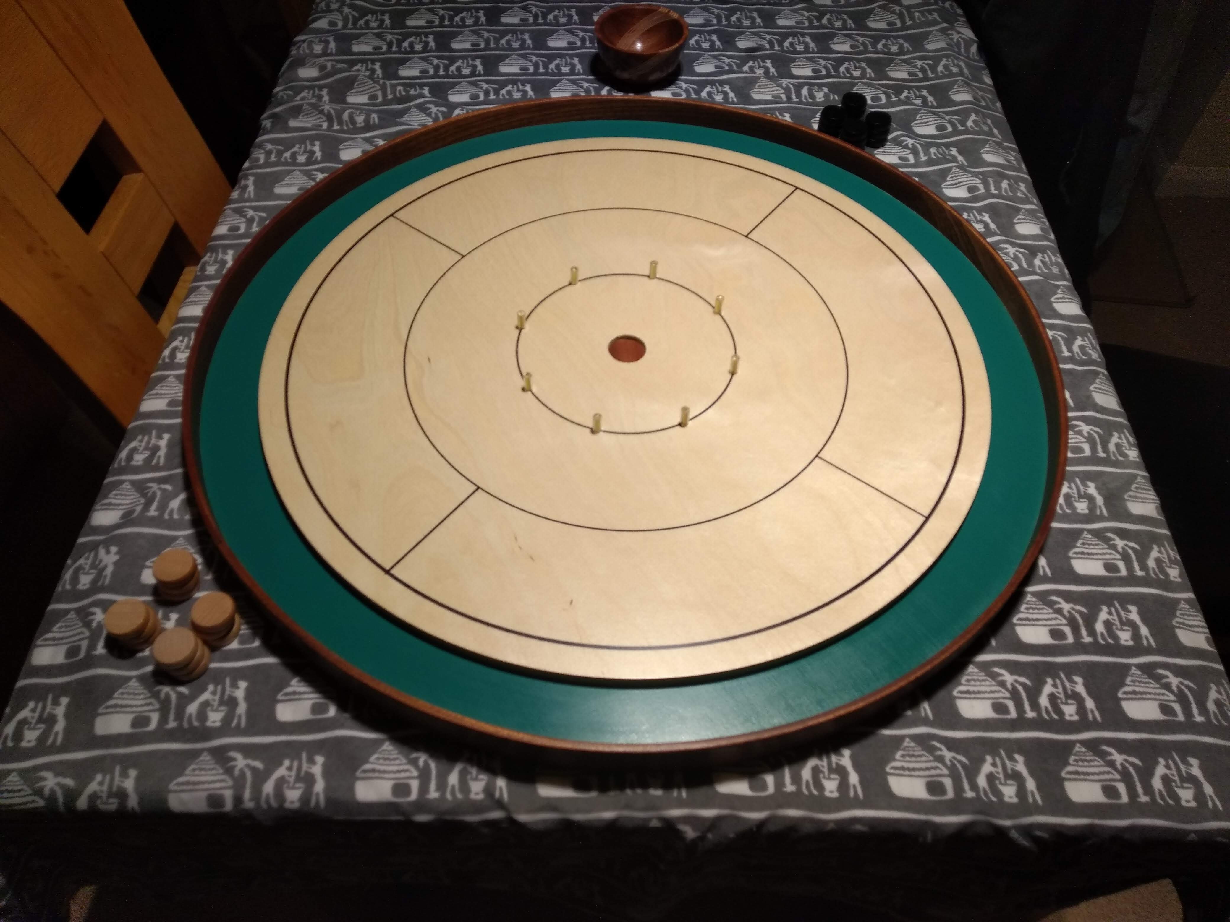
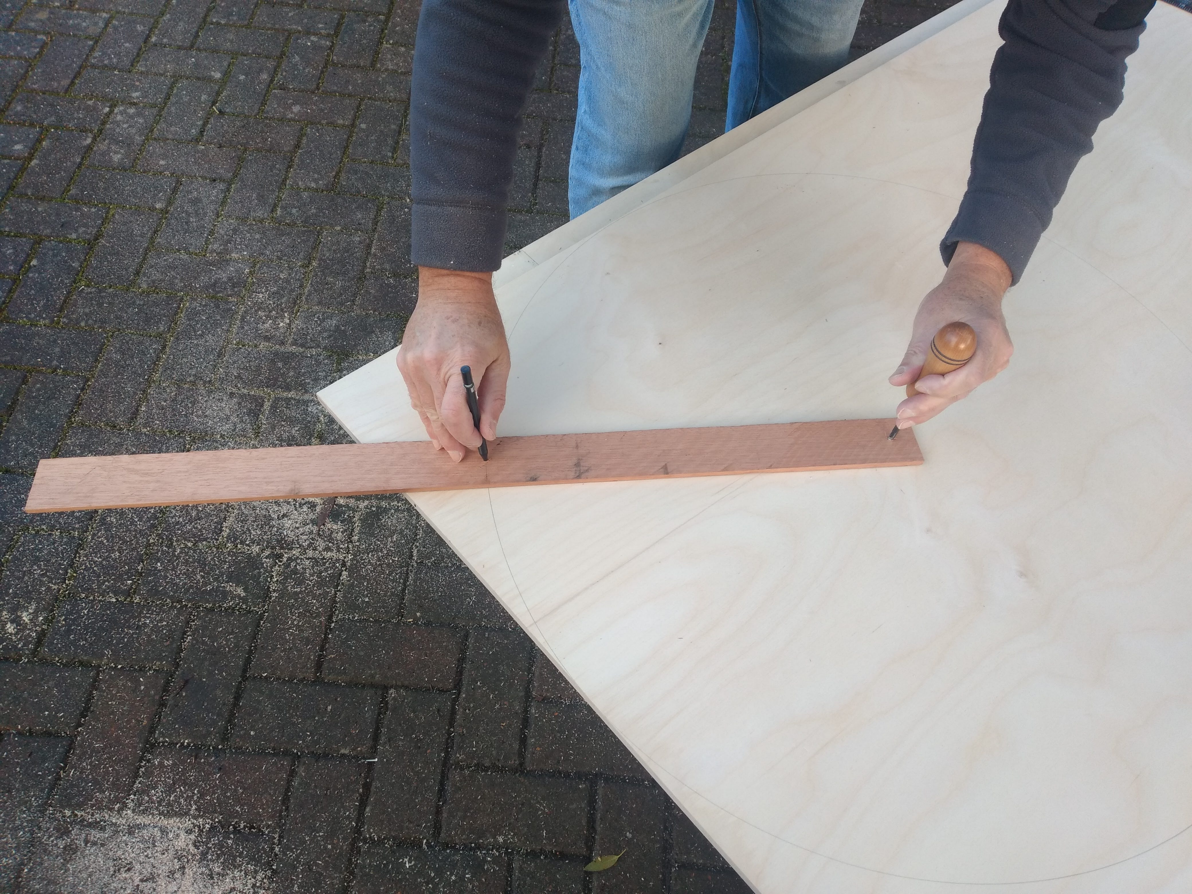
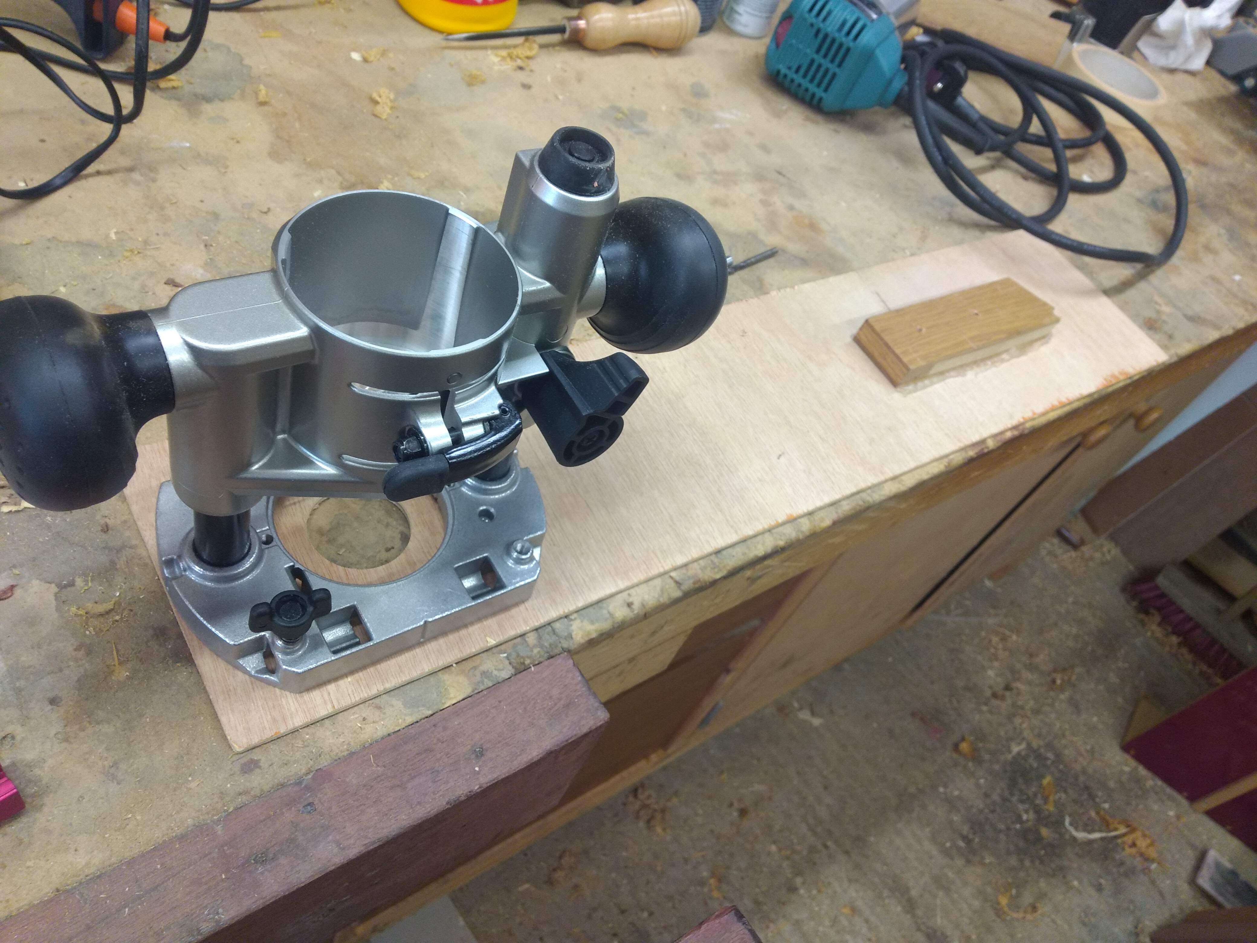
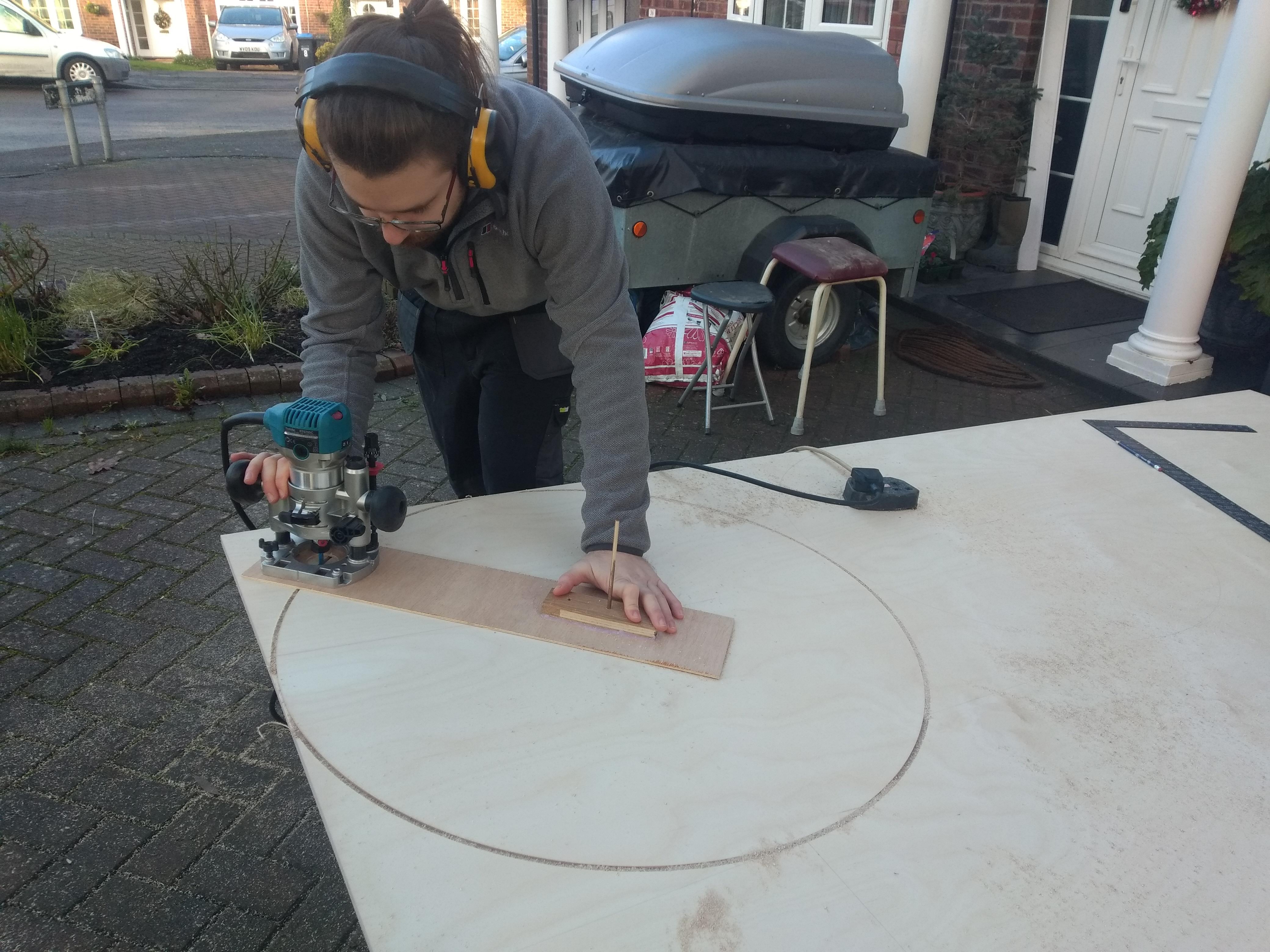
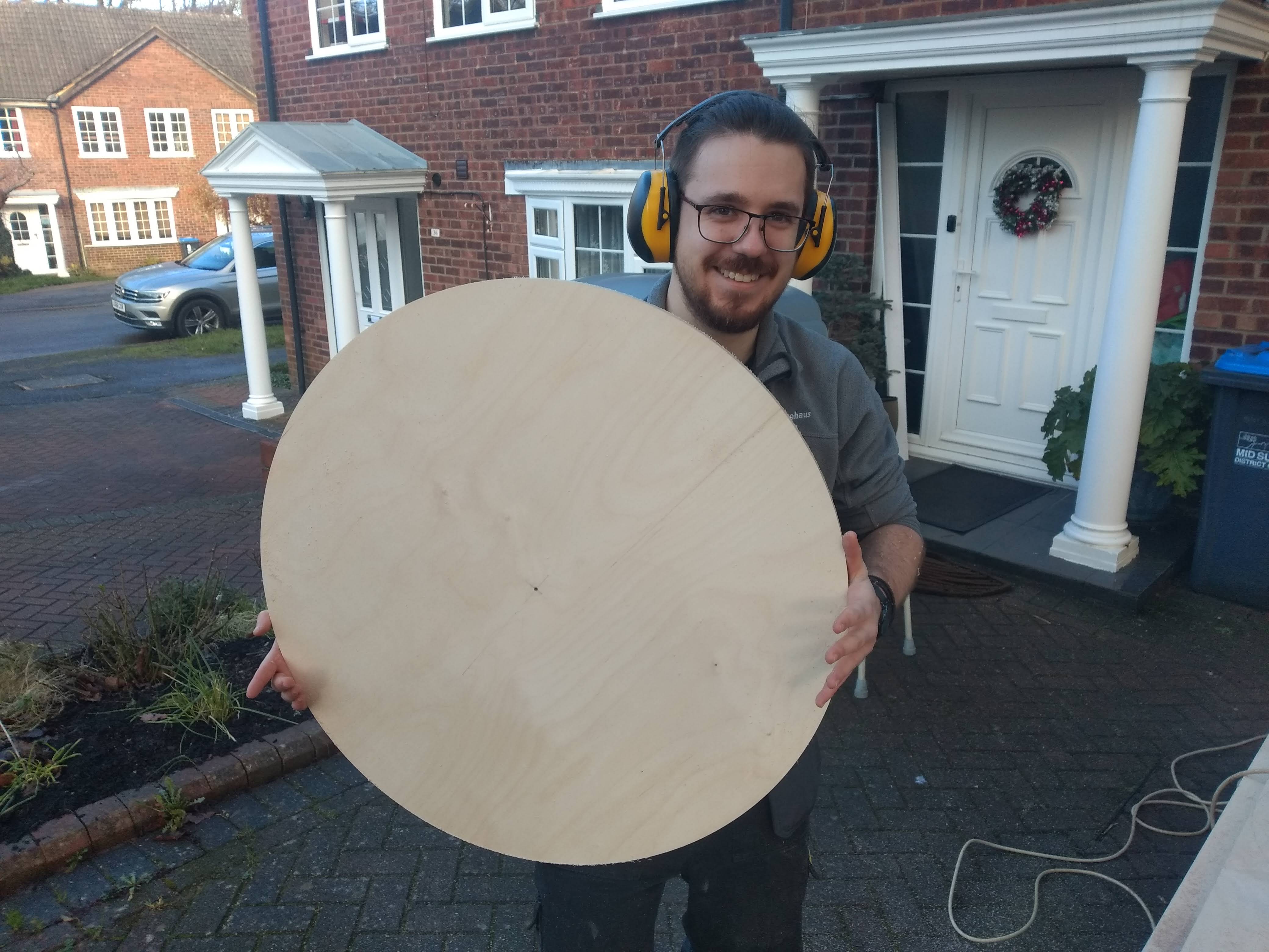
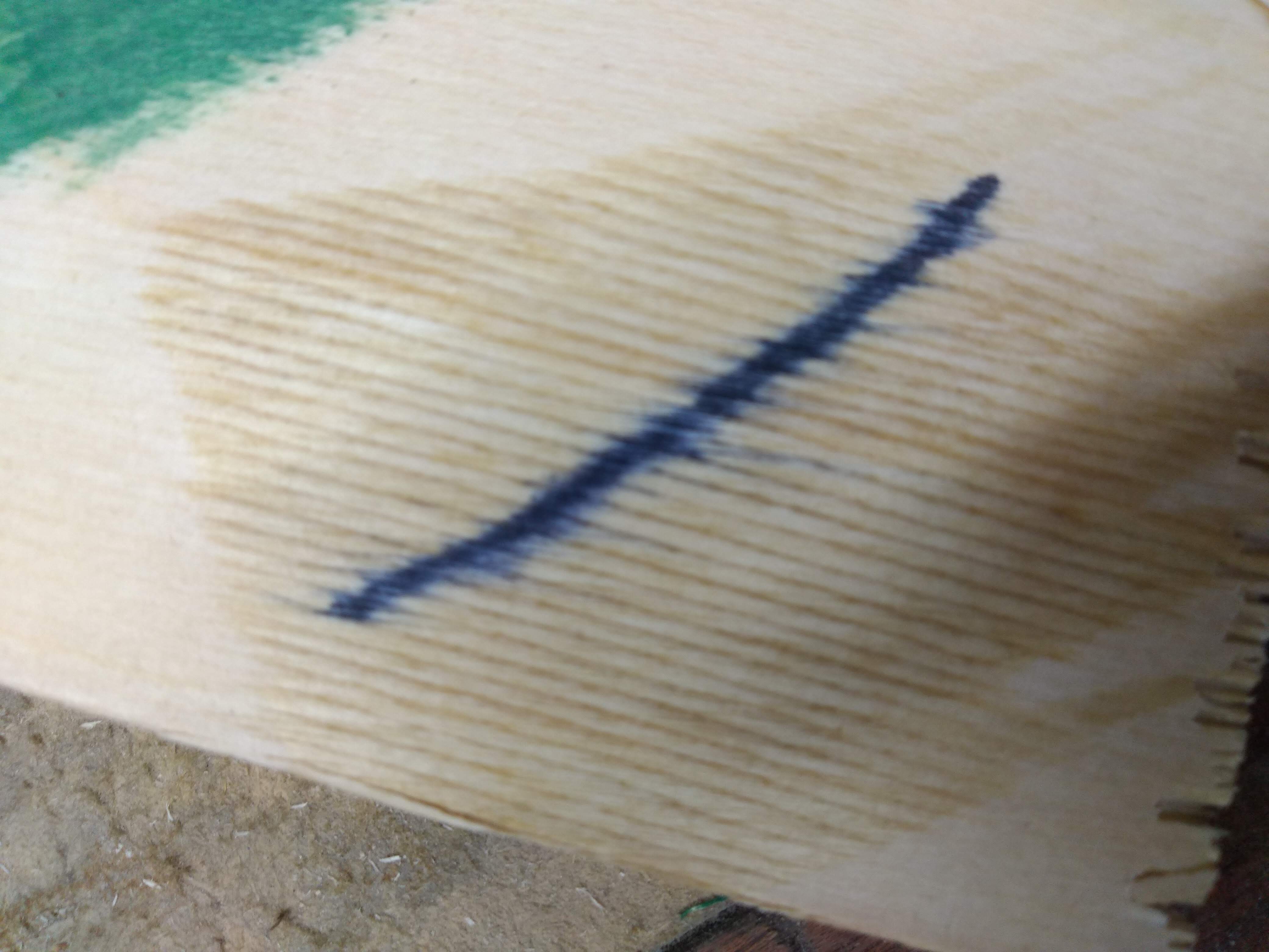
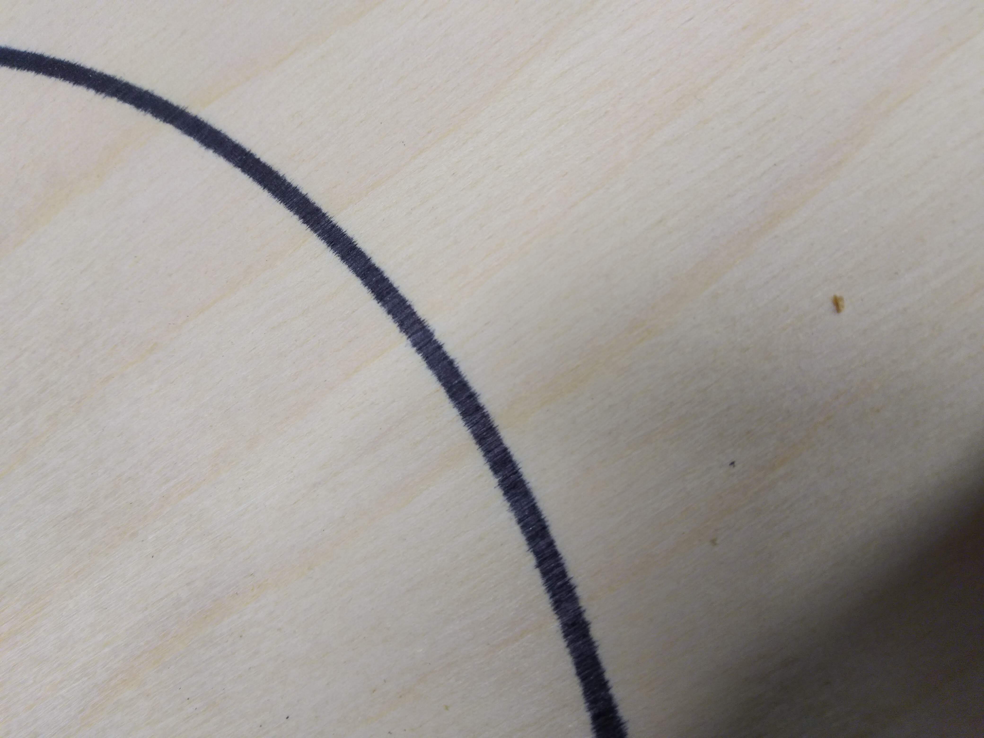
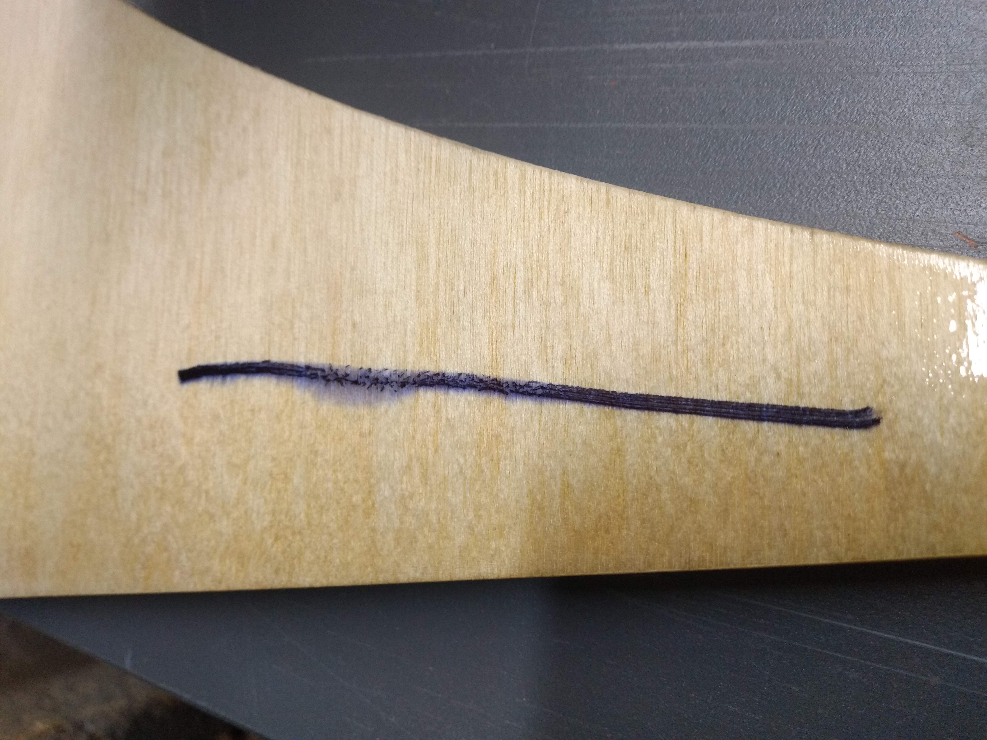
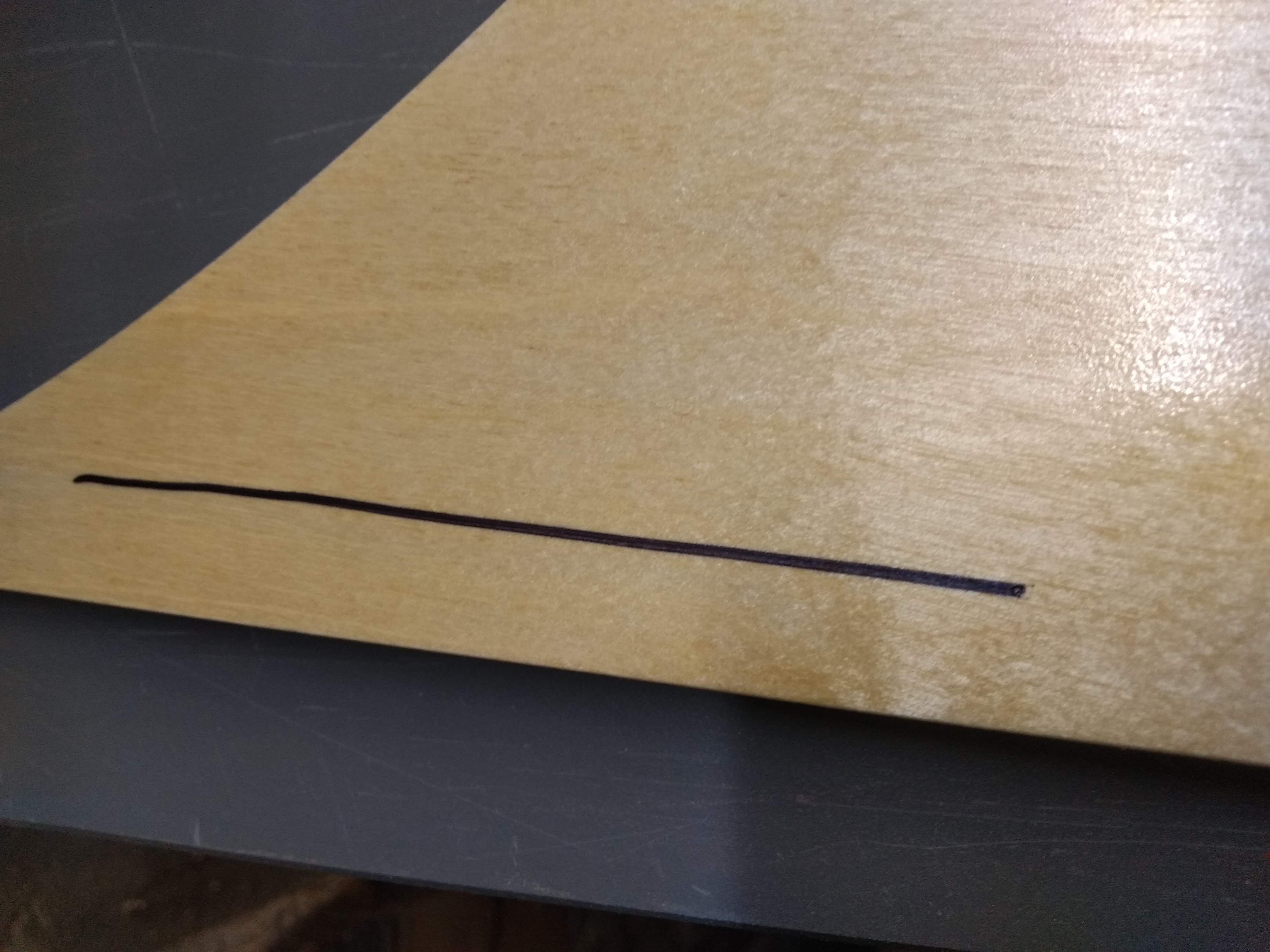
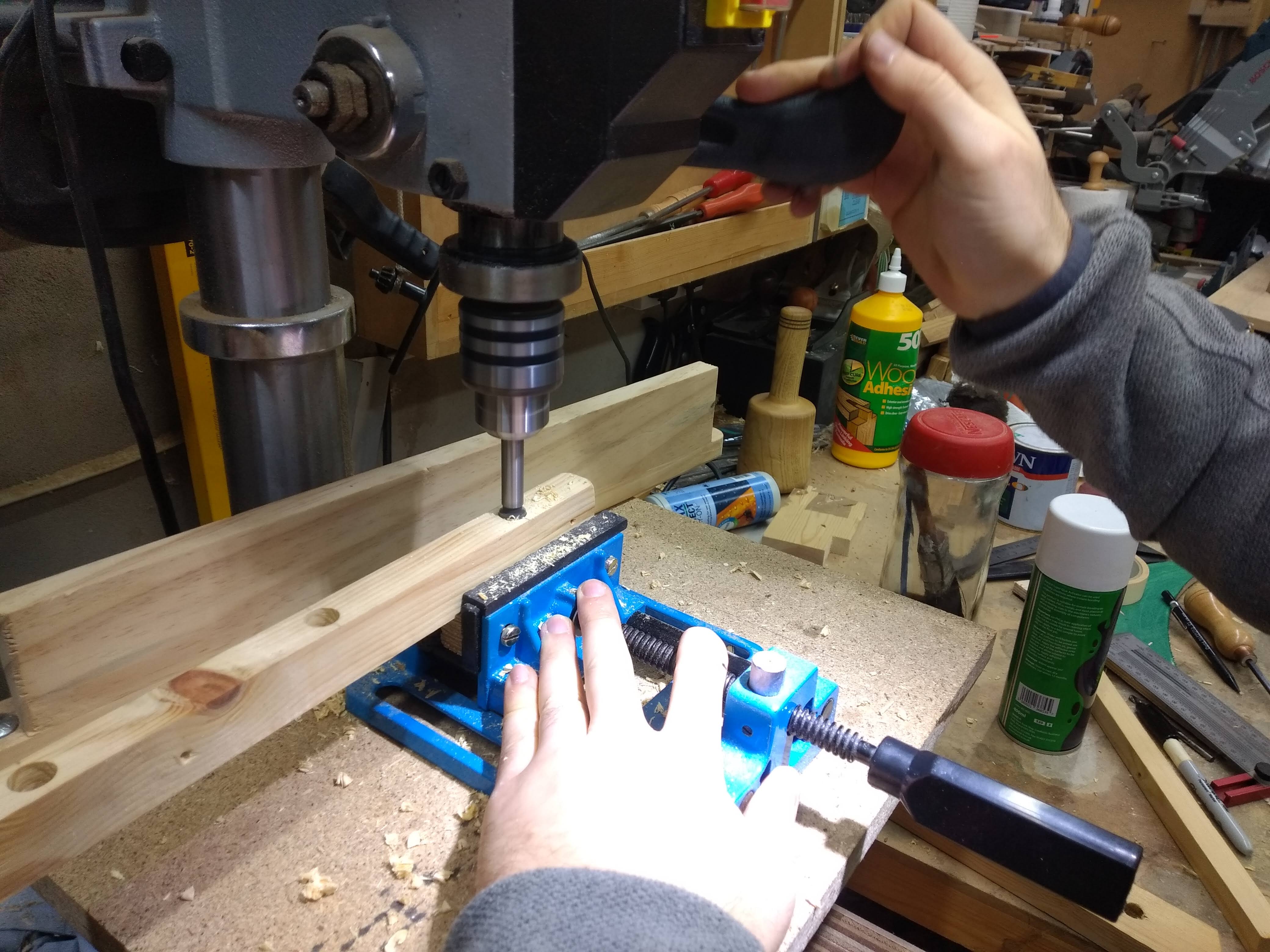
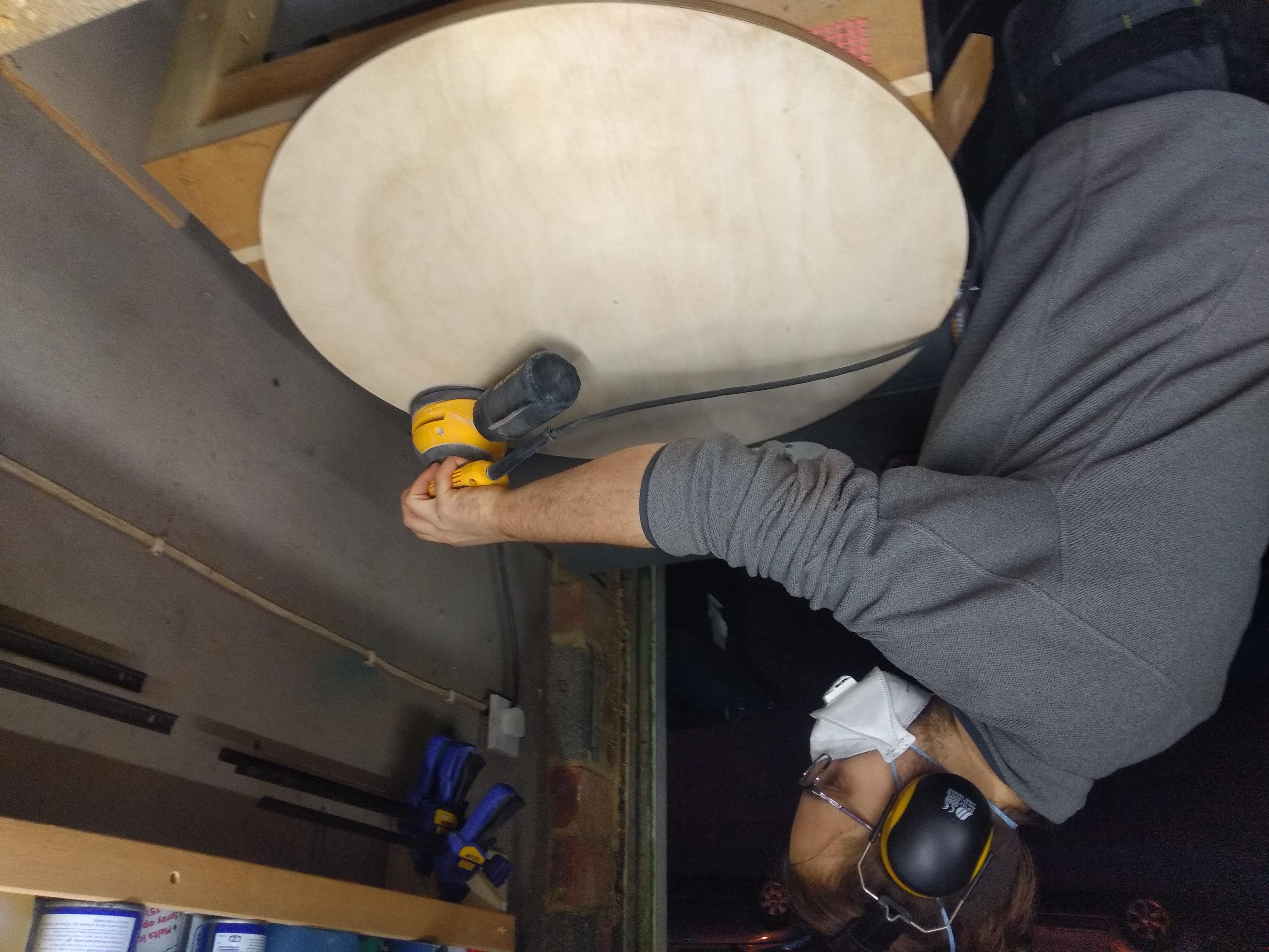
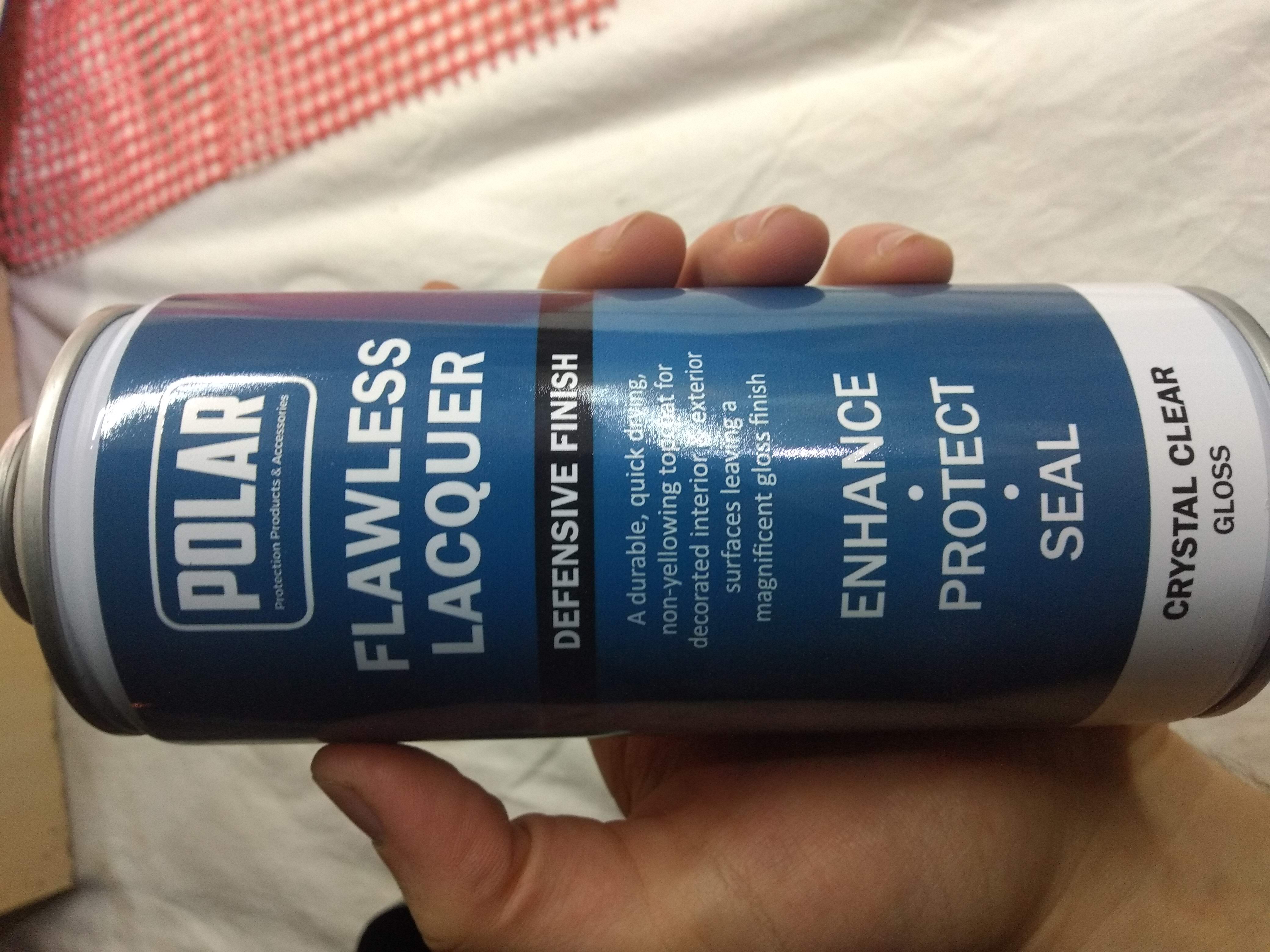
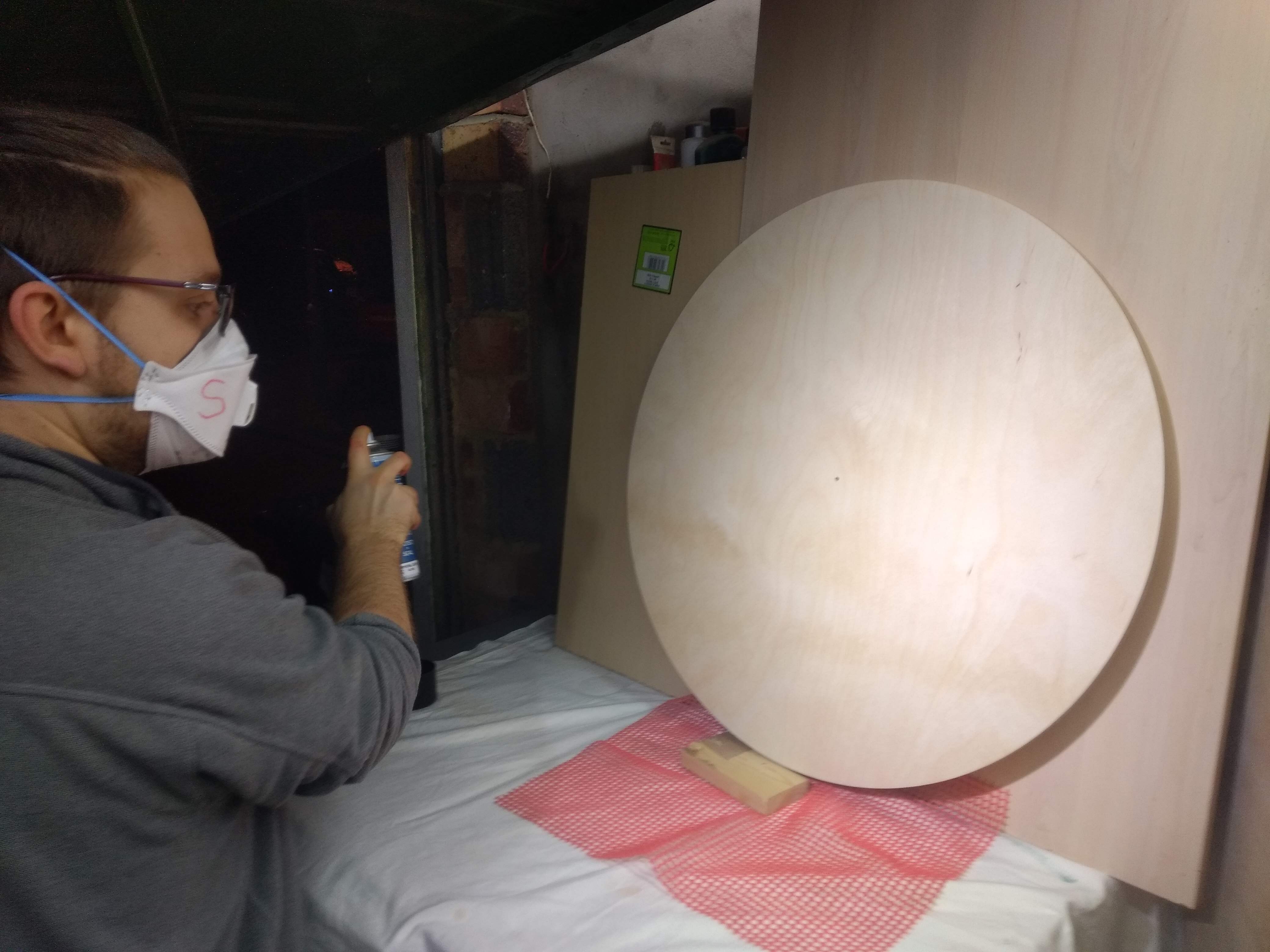
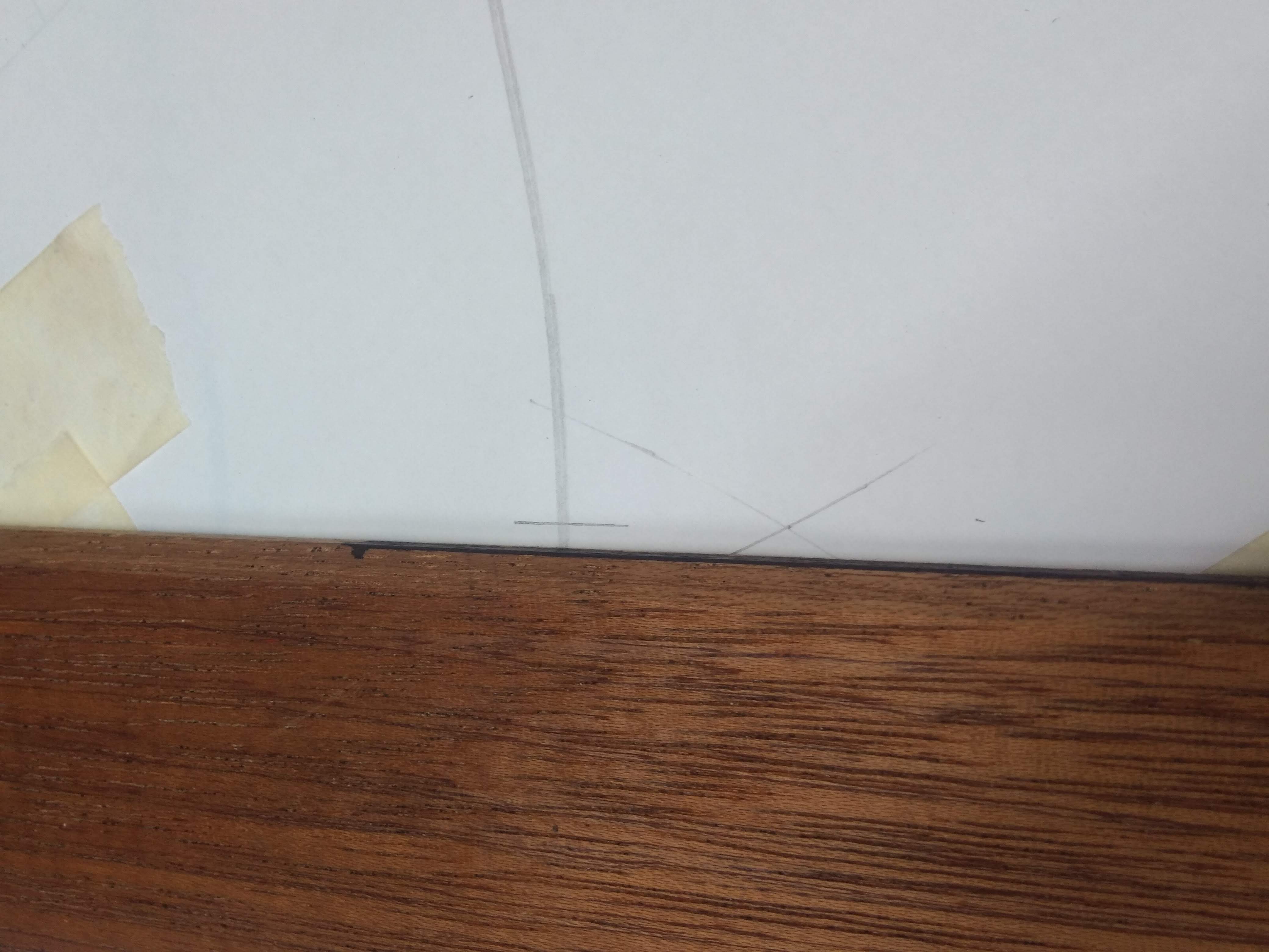
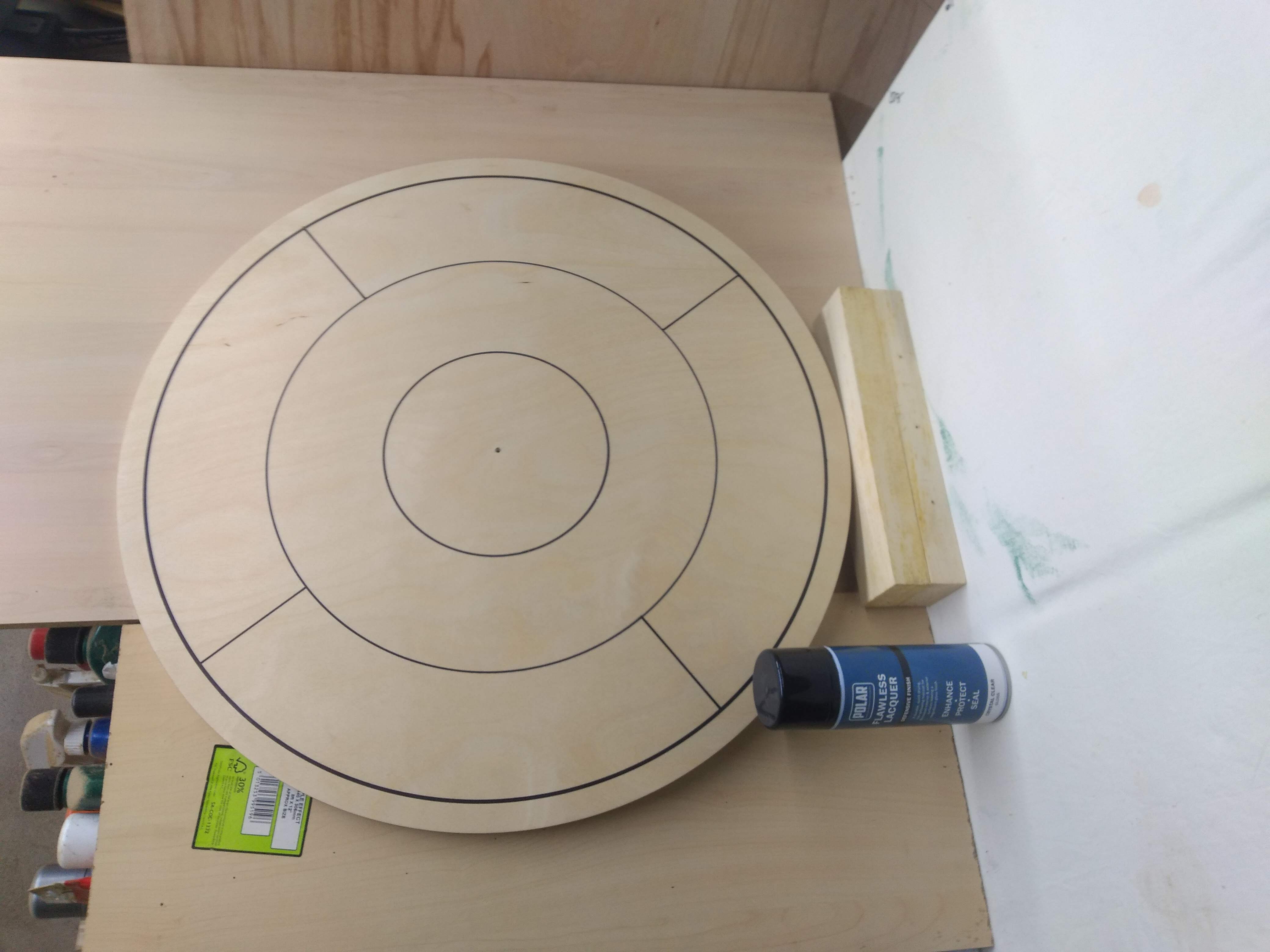
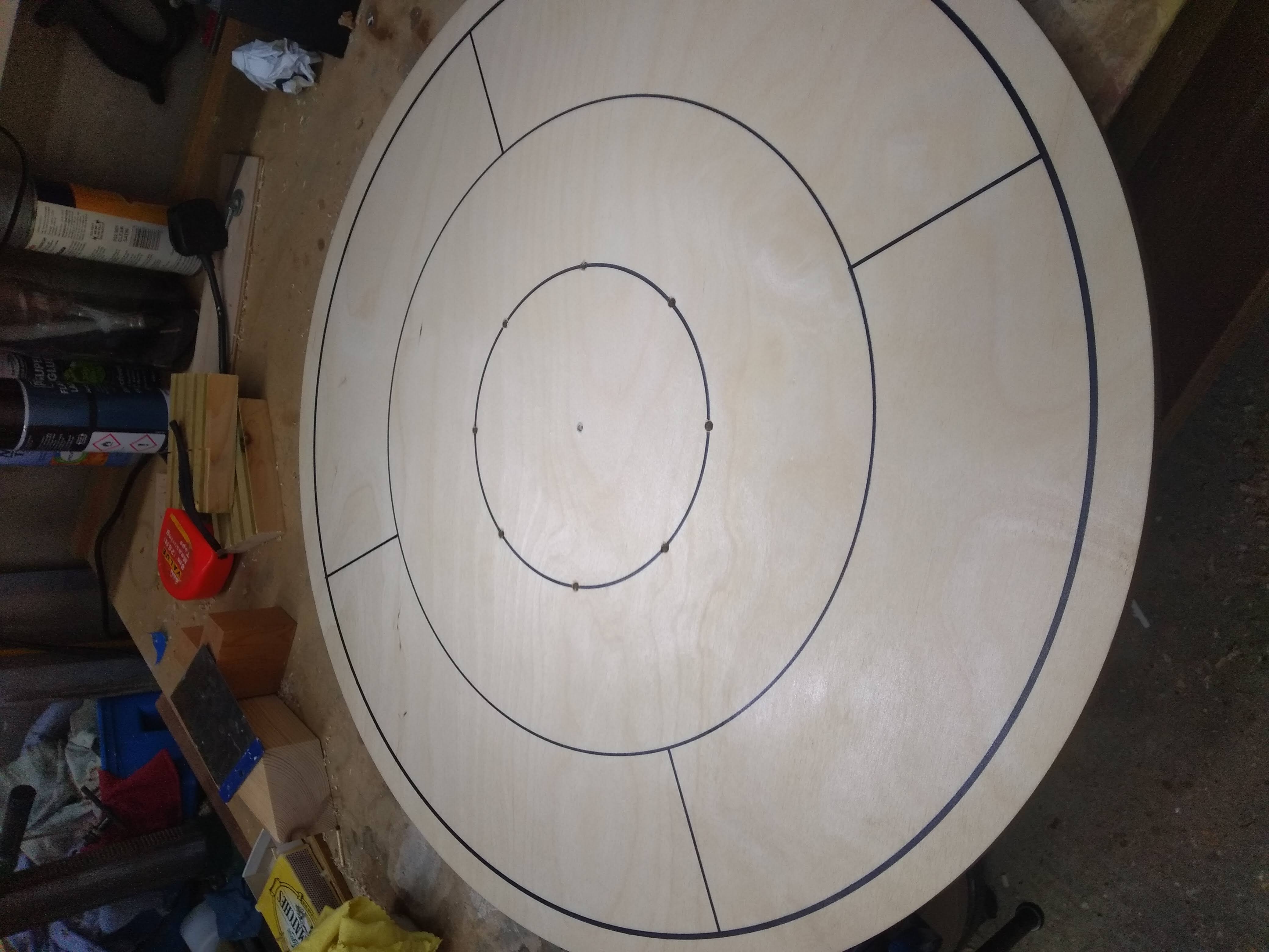
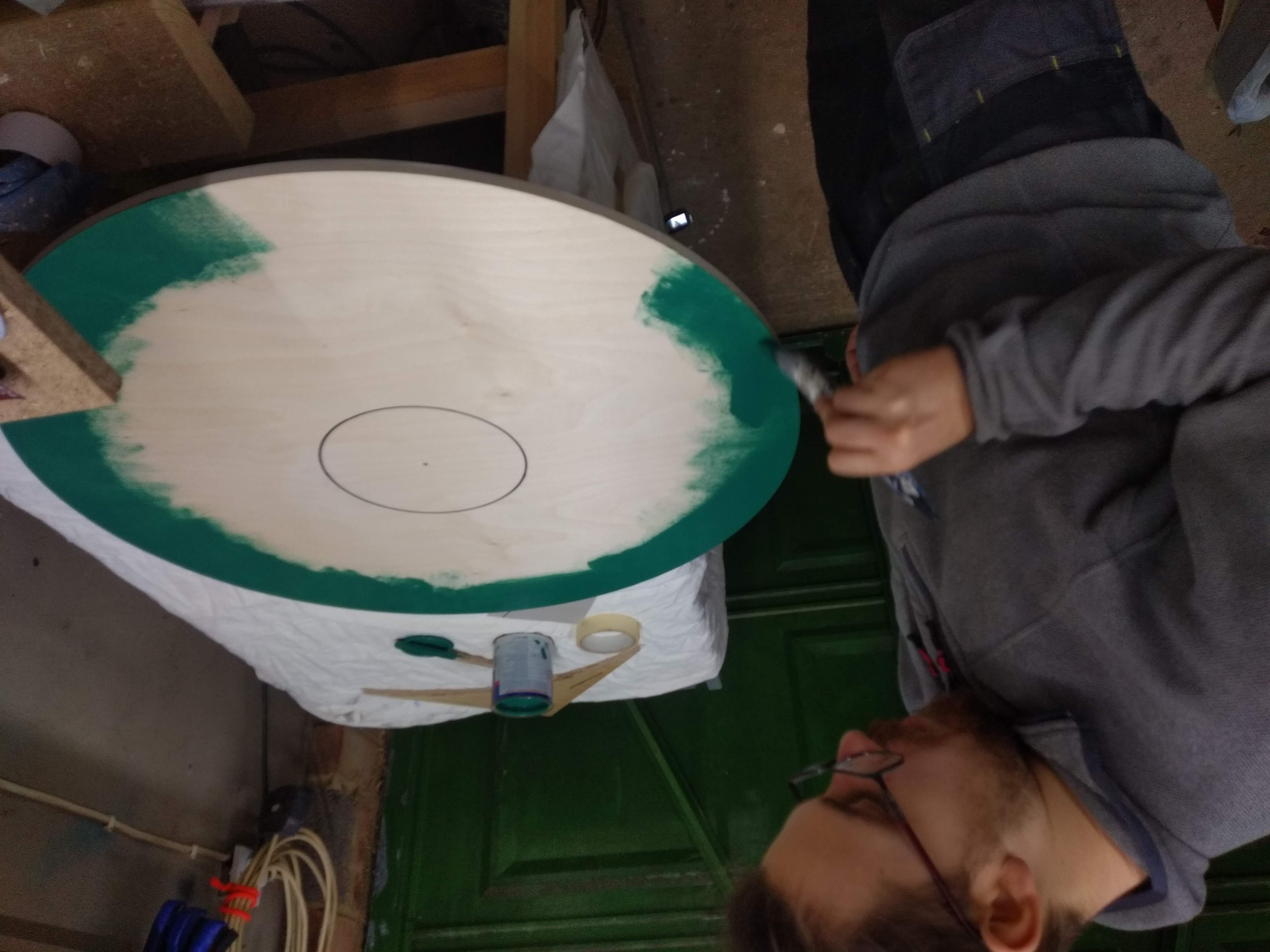
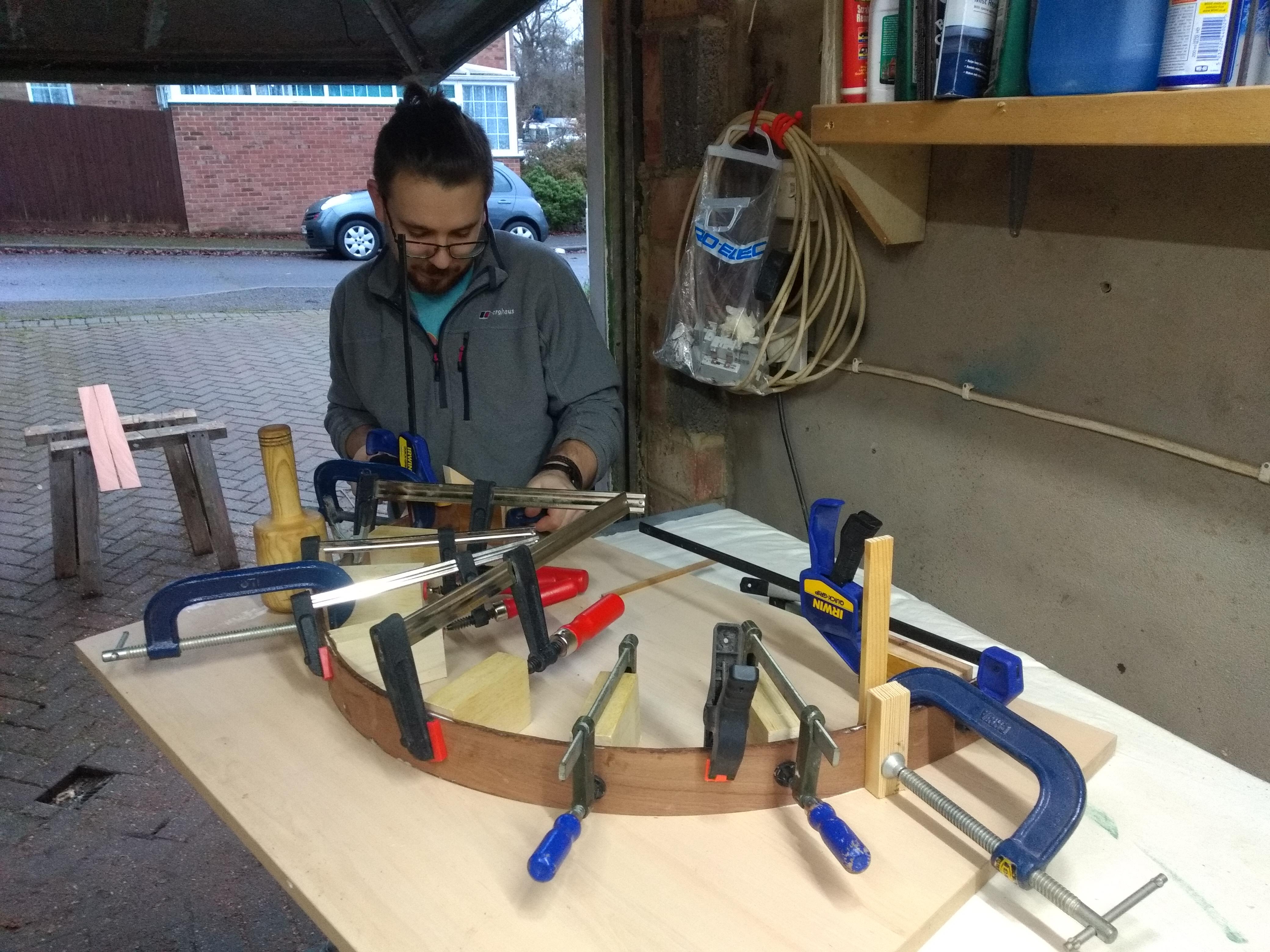
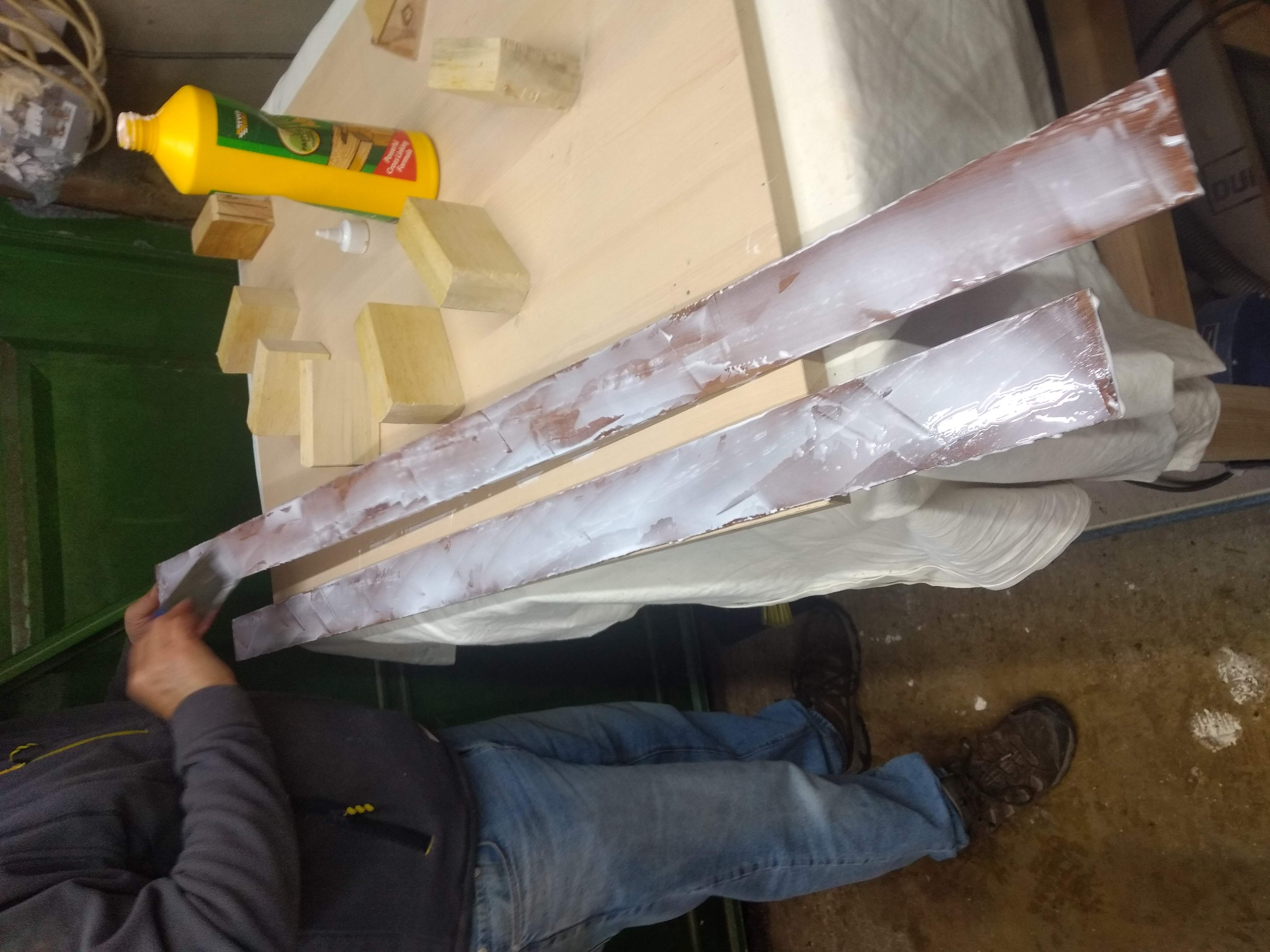
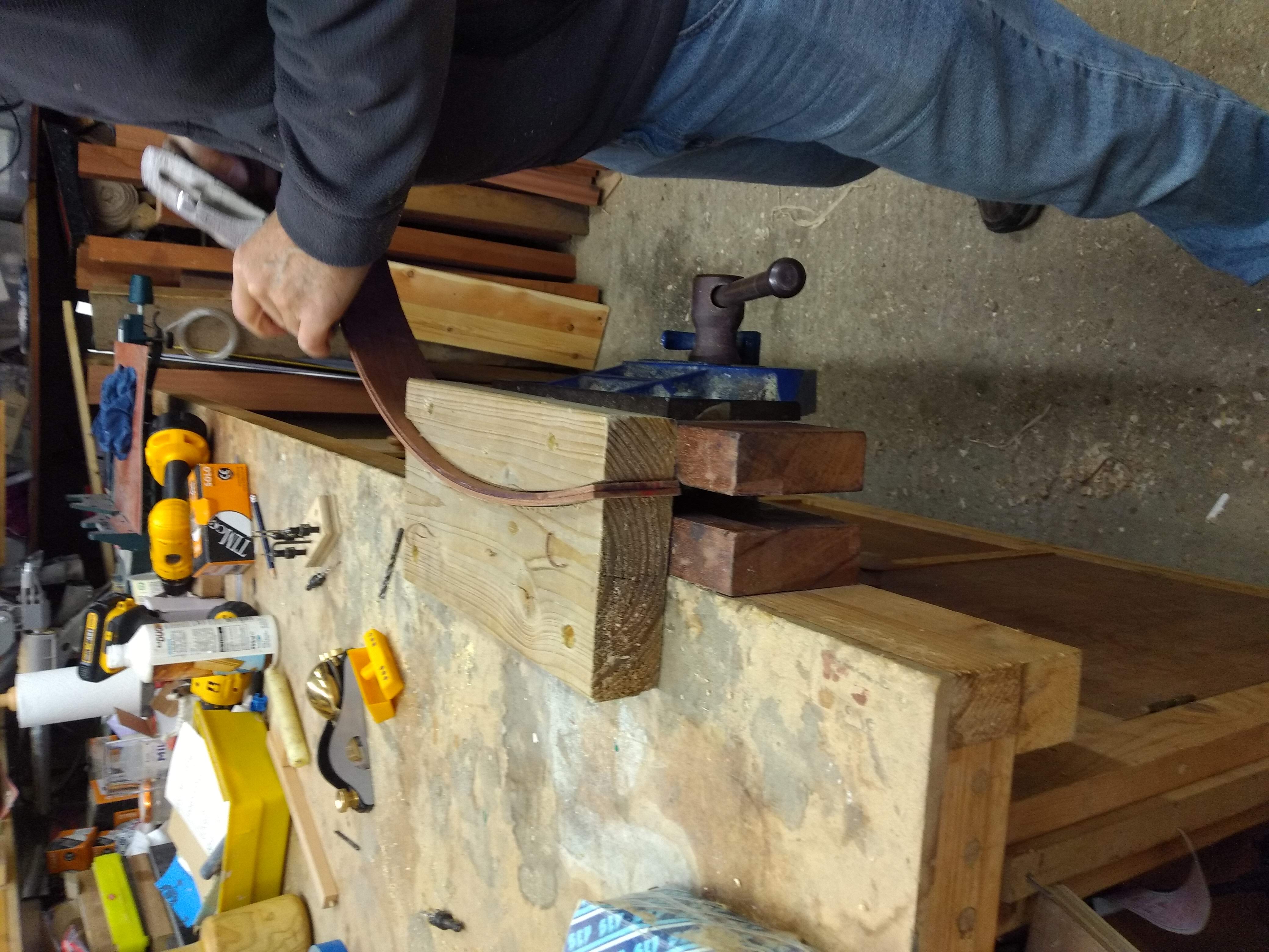
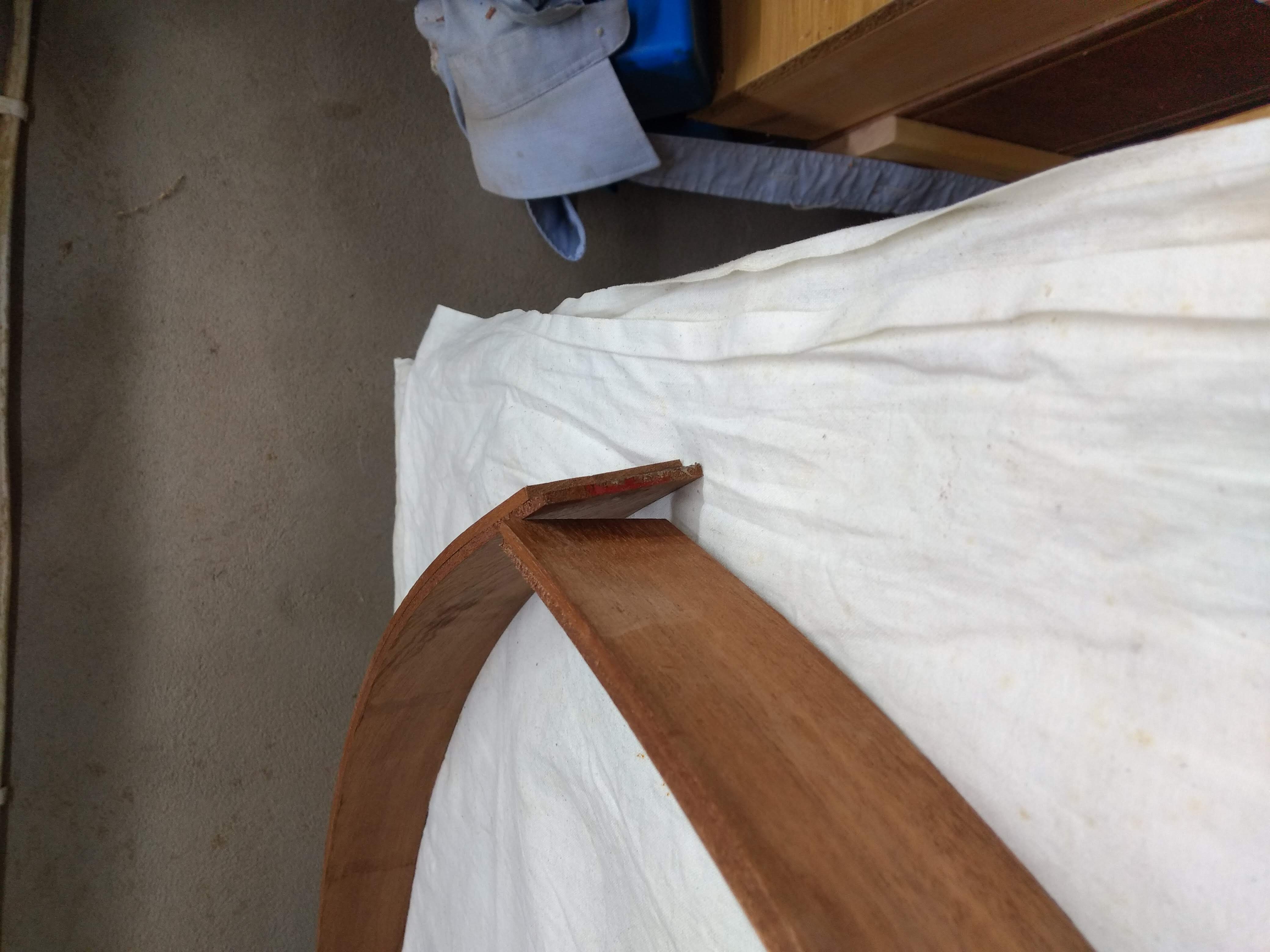
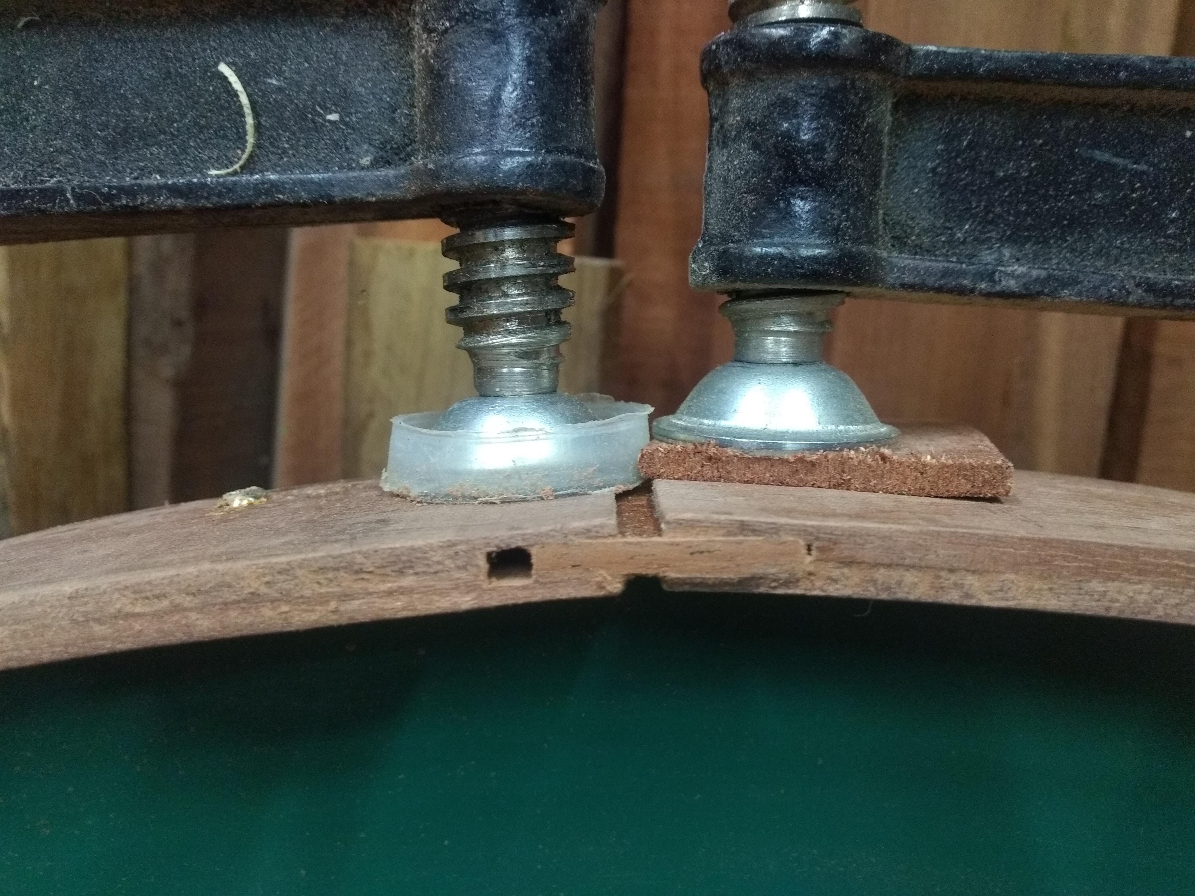
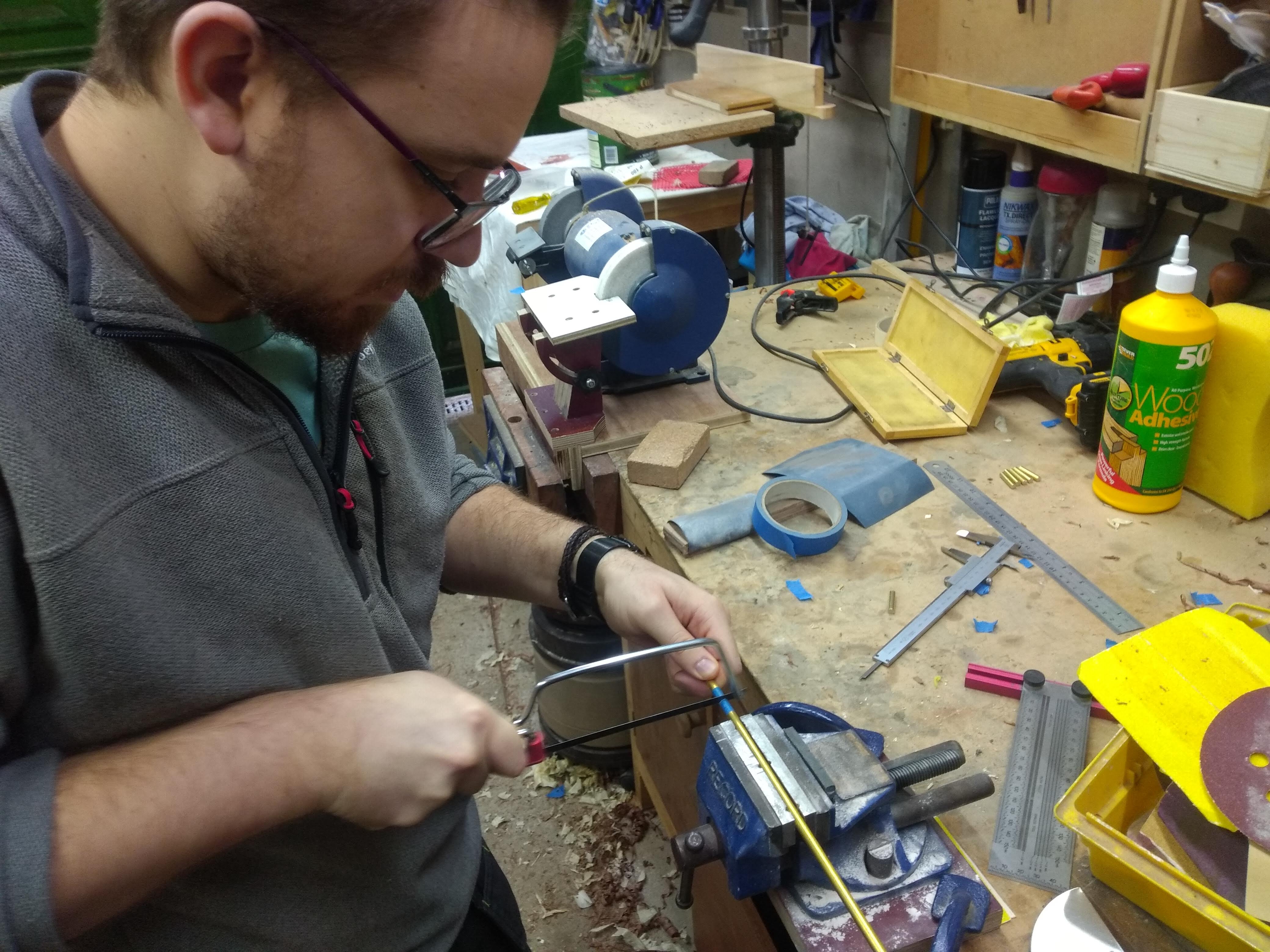
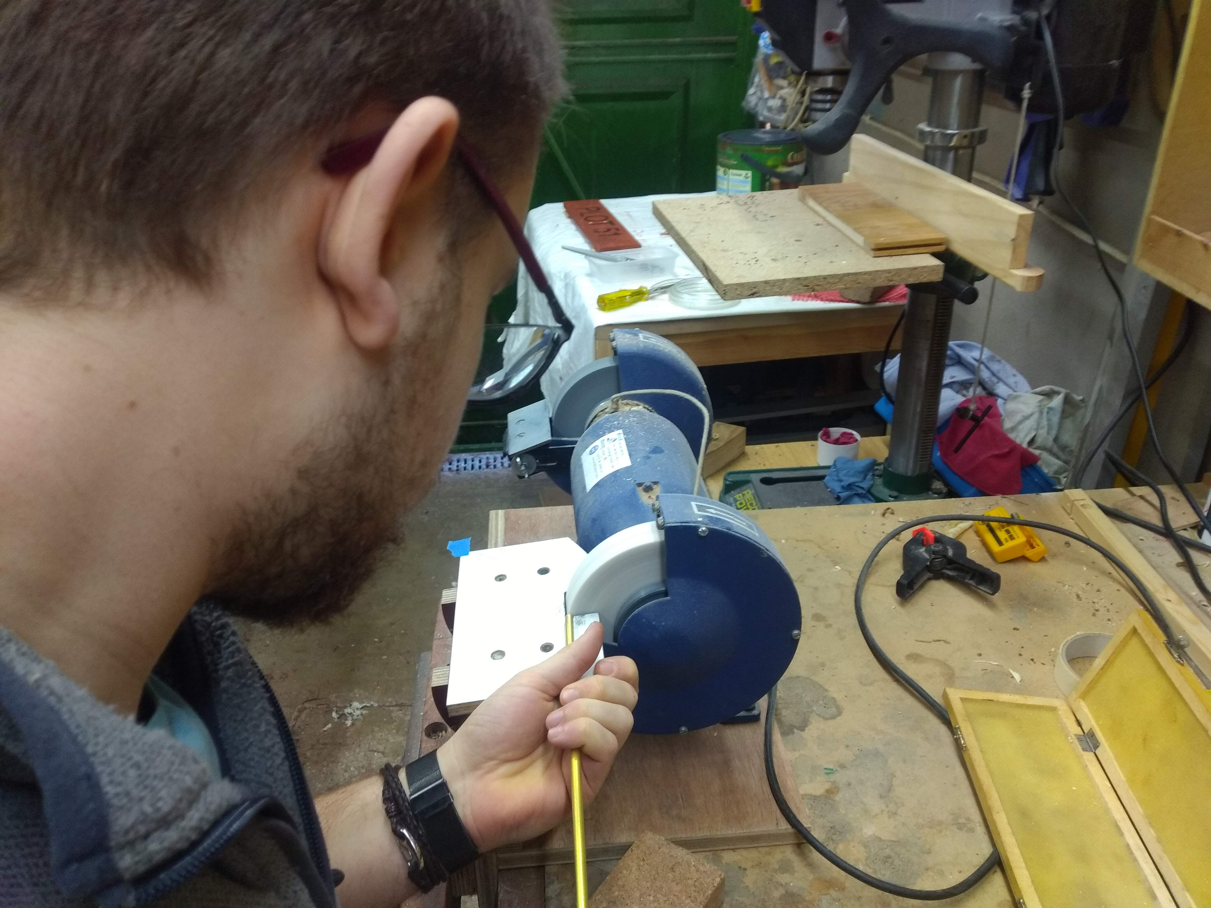
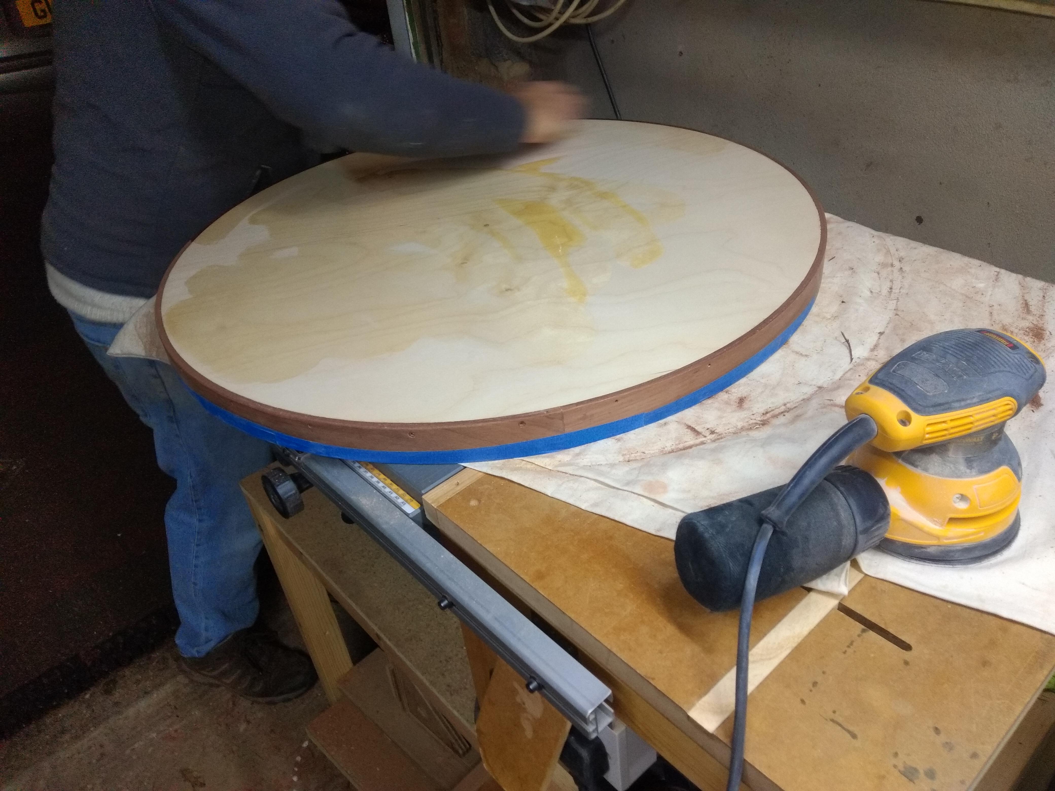
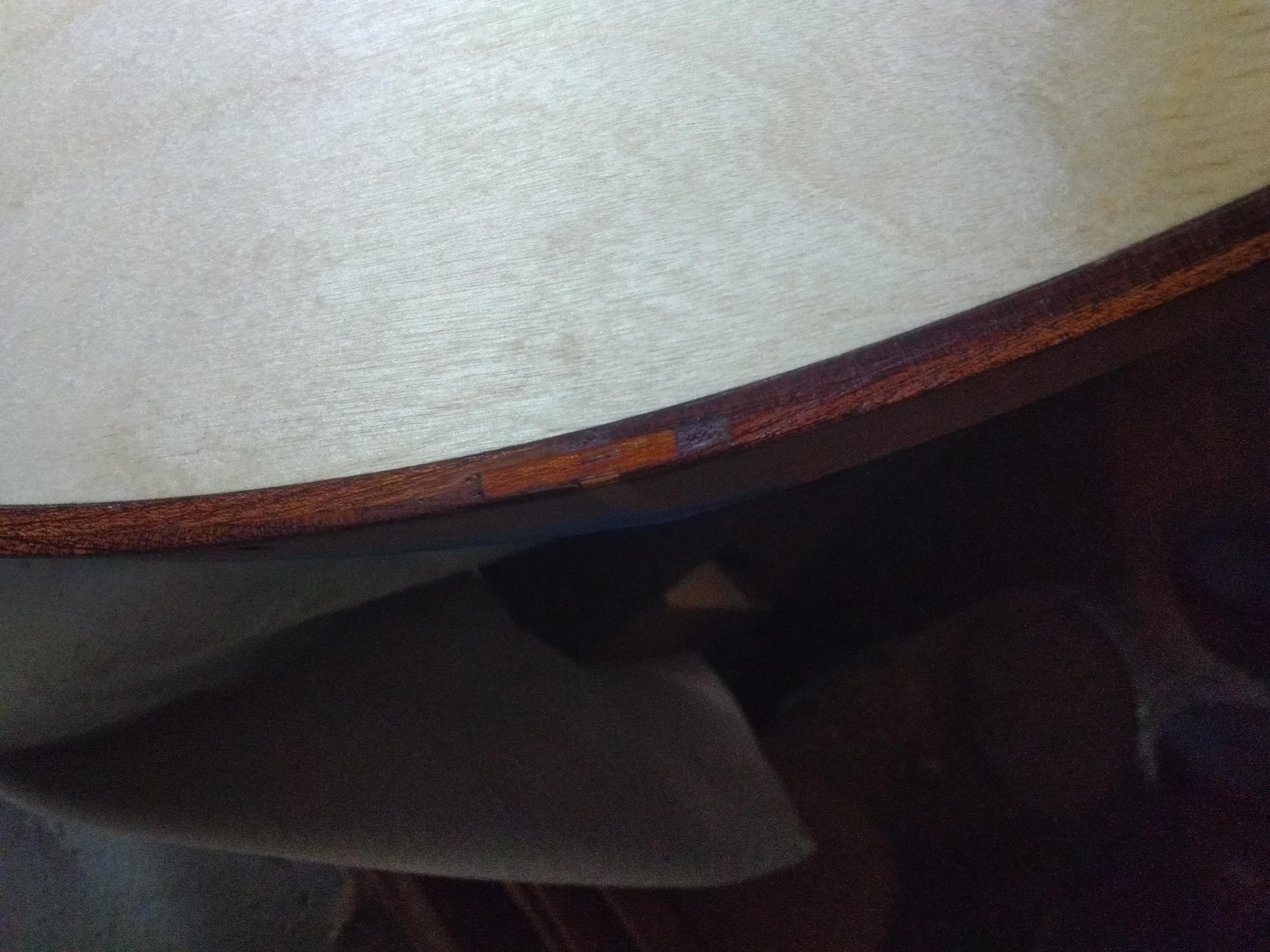
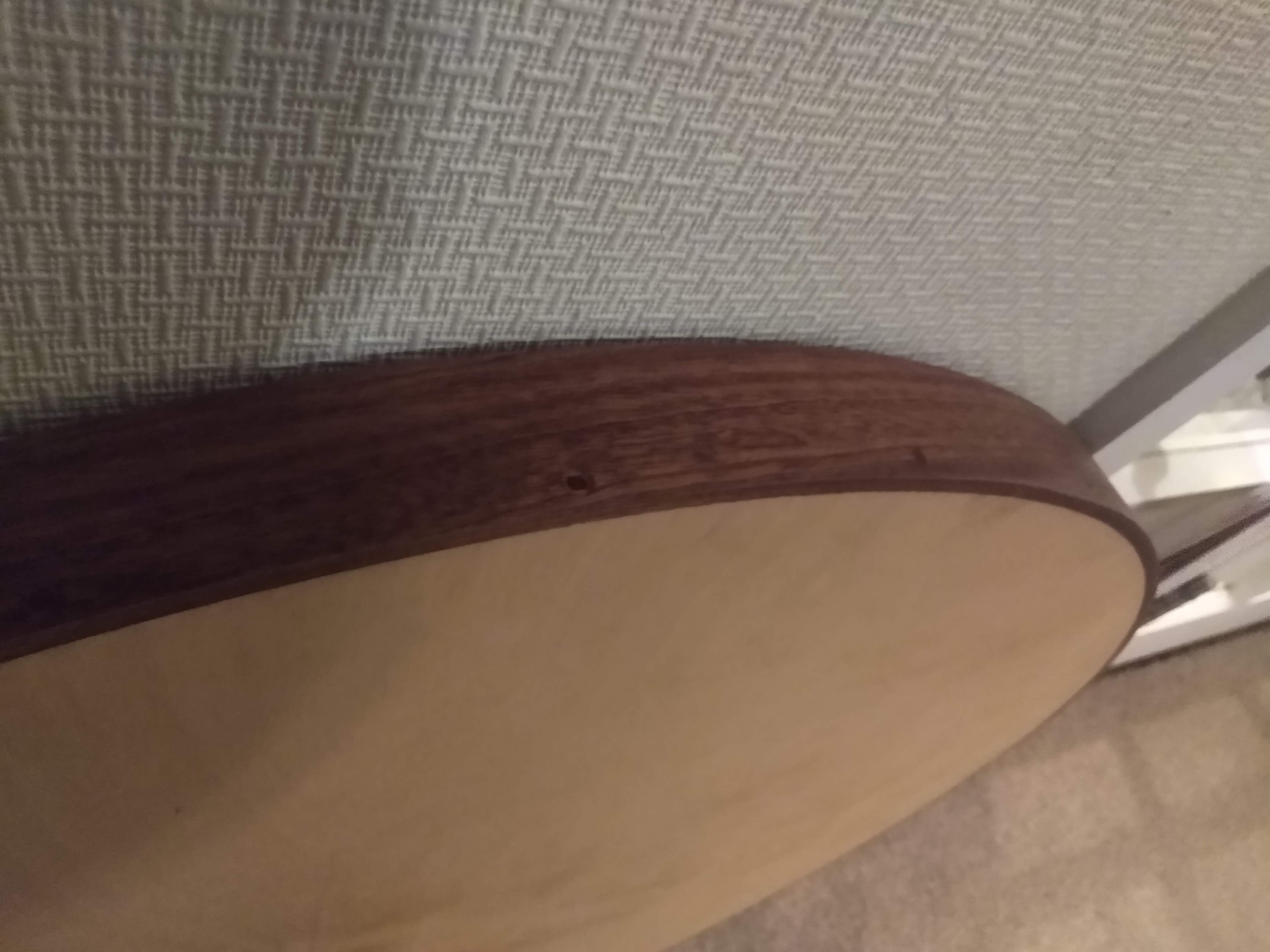
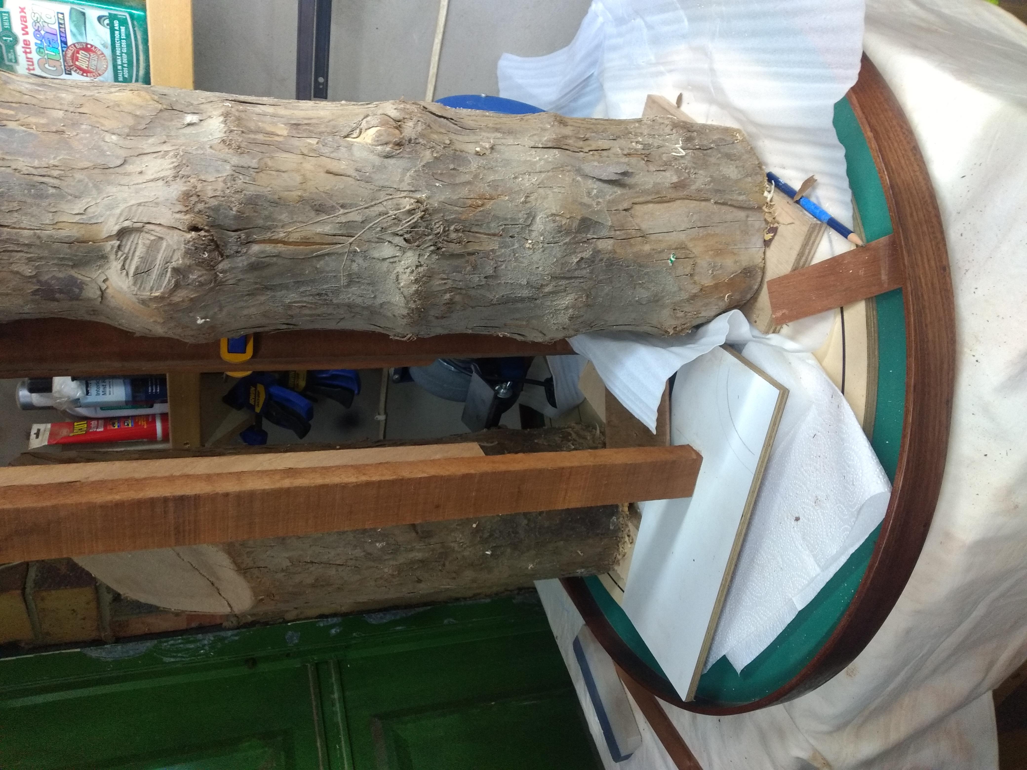
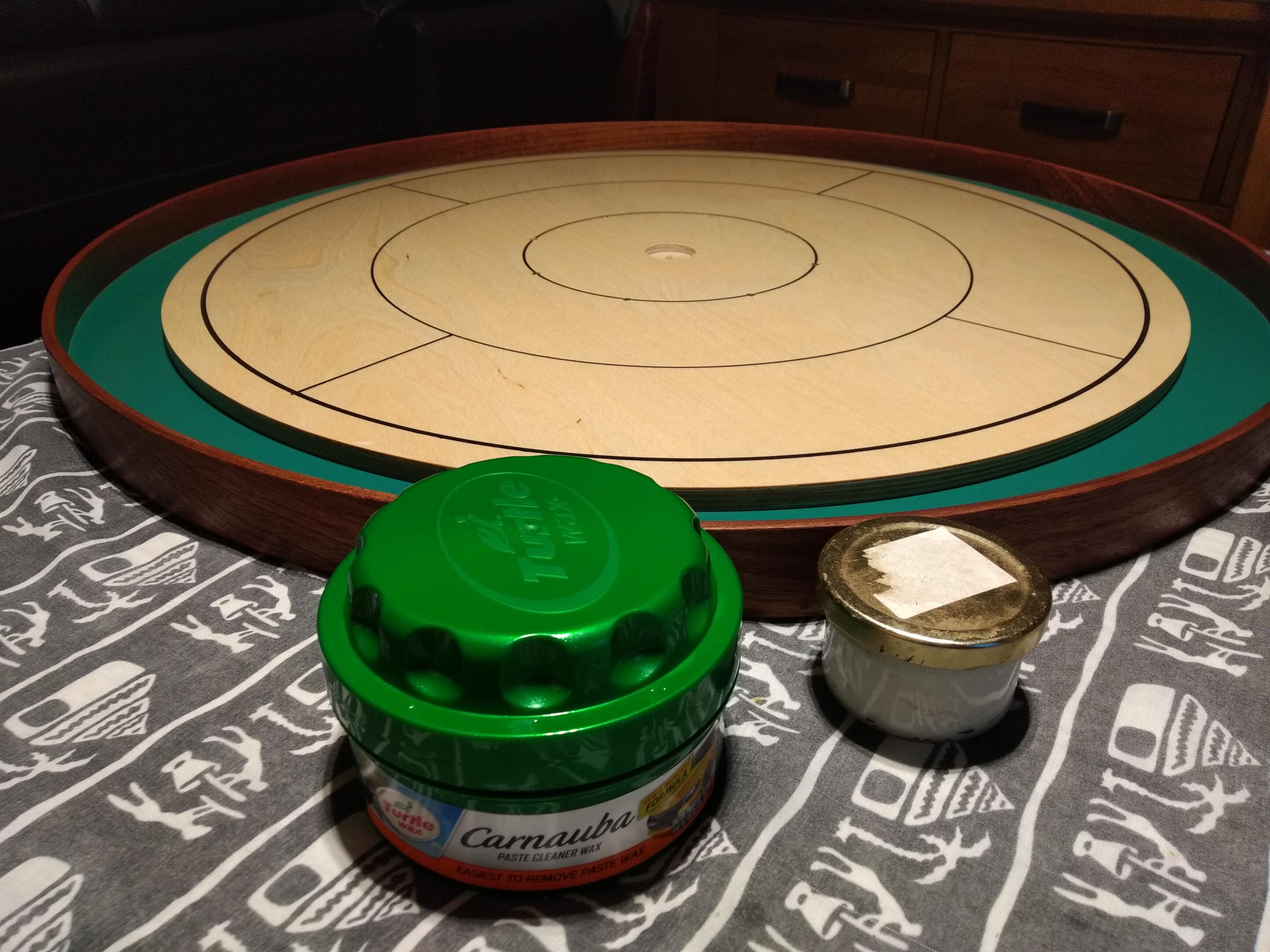
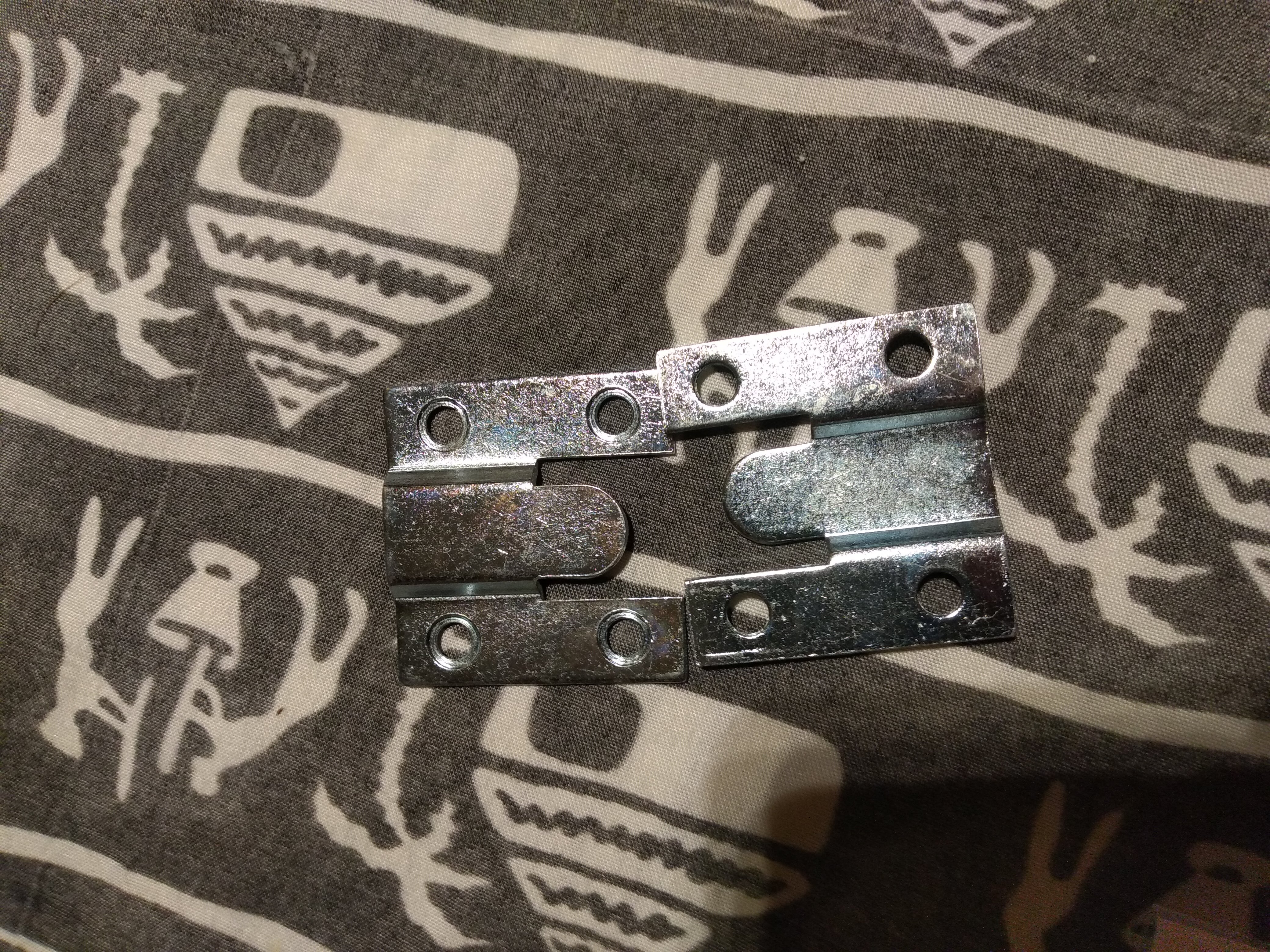
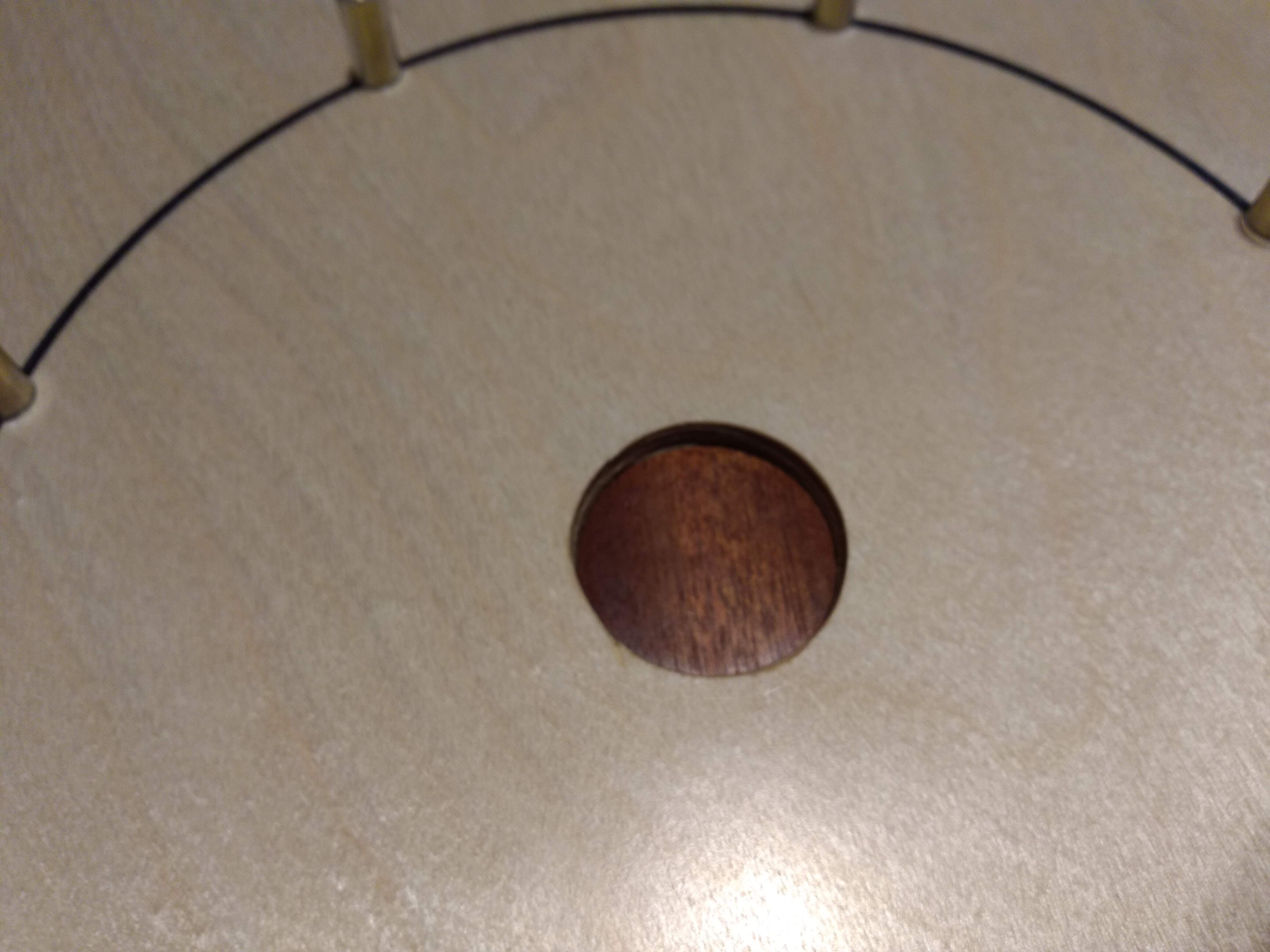
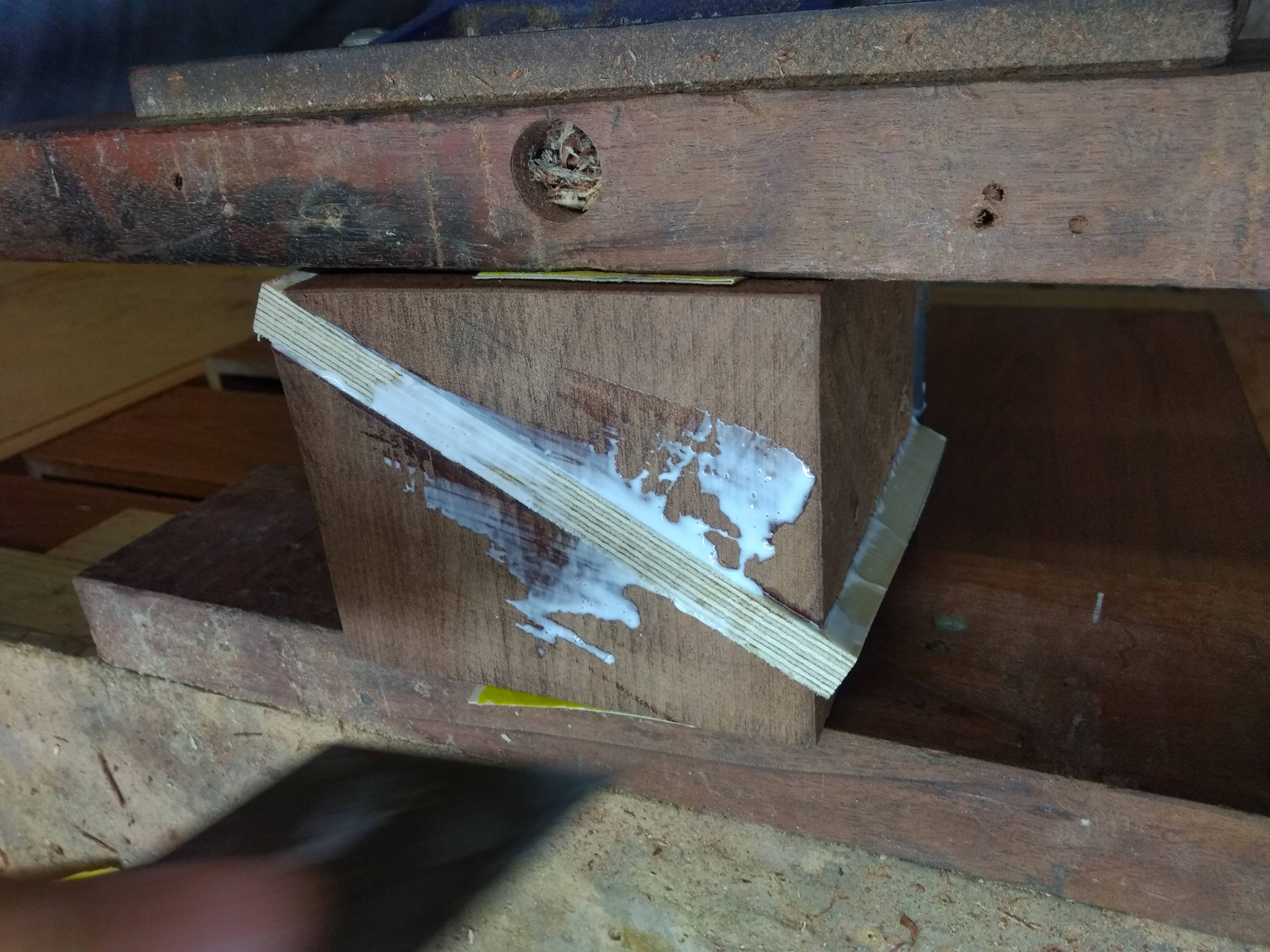
At the start of the my christmas break my dad and I got to work on the crokinole board. The plan was to cut the circles and bend some dark wood (for contrast) to the outside of the base to make the rim. The rim is typically made from flexible ply which makes it much easier to attach but for me the dark wood contrast is worth the stress. It is an ongoing debate in my head as to whether the centre should have been plugged with a dark wood or green-painted disc (feel free to help me settle this in the contact me form below). The two circles for the playing surface and the base are cut from 1/2" A grade birch plywood. The rim, plug-disc and bowl are made from kiln dried iroko. In my case the pins are 6mm brass rod with a sleeve of 8mm OD clear PVC tubing. Our central hole was cut with a 35mm forstner bit because we didn't have an imperial set and there's only 0.075mm difference (much smaller than the uncertainty on the cut). The playing surface was finished with spray lacquer, then the lines were drawn with Sharpie brand permanent marker, and topped with more spray lacquer applied very thin to avoid blotting or bleeding of the sharpie ink (see images 13-16). This was sanded before paste wax was applied and very fine steel wool was used to buff the wax. After some test games, some jelly carnauba wax was applied and this was buffed with a cloth. A stripe of "poker table green" gloss paint was applied to the trough area of the base (multiple coats, sanding between each) because the board looked strange without contrast and we did not like how dark stains looked on this wood. The rest of the board was finished with danish oil and elbow grease. After a few weeks, this top coat was sanded back with 1000 grit sandpaper and multiple coats of fresh carnauba wax. This resulted in a very fast playing surface which came with its own issues: the discs would float on a cushion of air and always go too far, but once they stopped they would stick to the board with a suction cup effect making them very difficult to move. To fix this, gliss powder (a lubricating wax powder) is applied to the discs before each shot. The result is nearly as good as air cushion glide but without the stiction issues once the discs come to a stop. The discs were simply bought from Woodestic via ebay. They are 10mm thick where some suggest they should be 3/8" but that's basically the same.
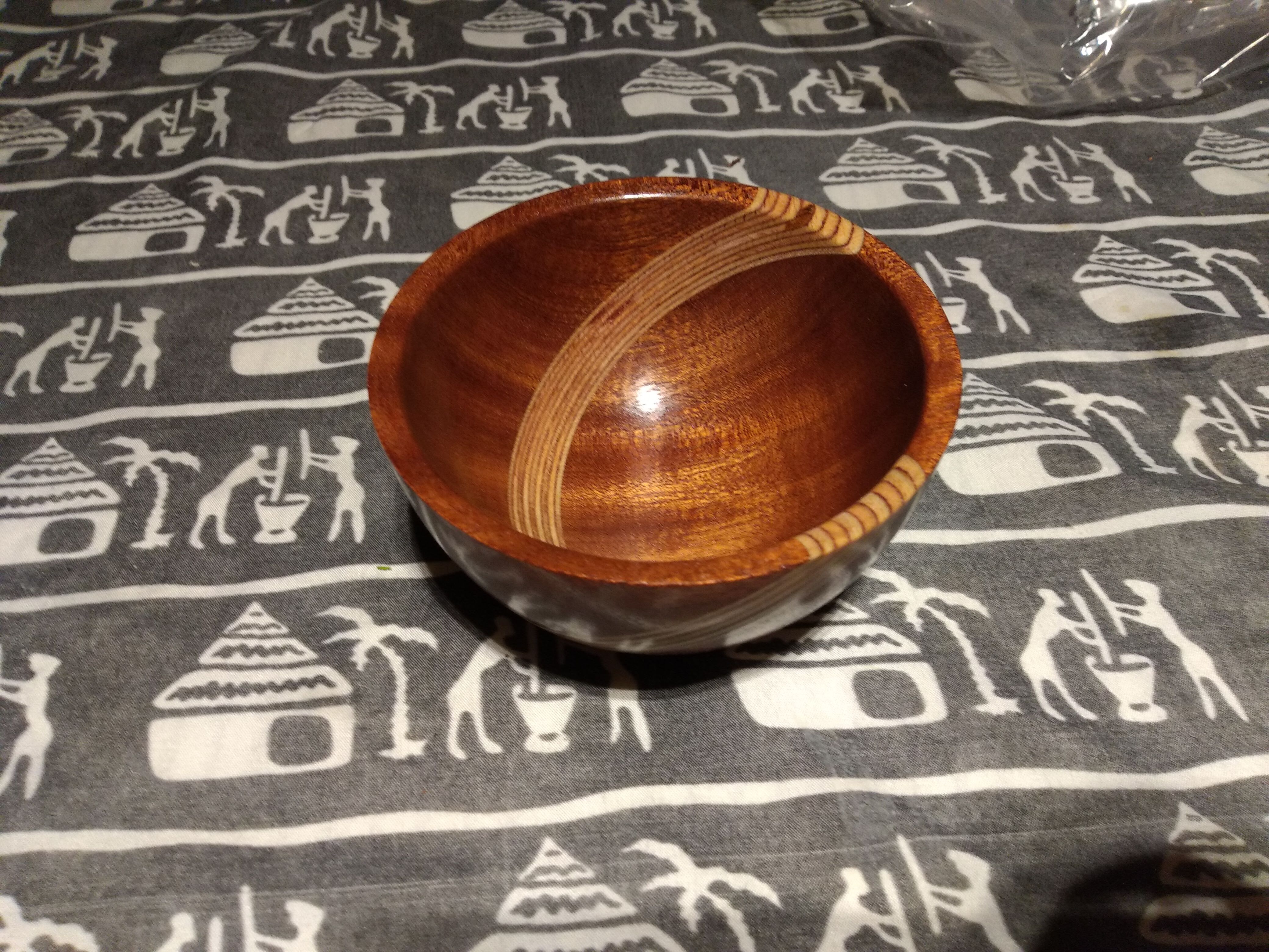
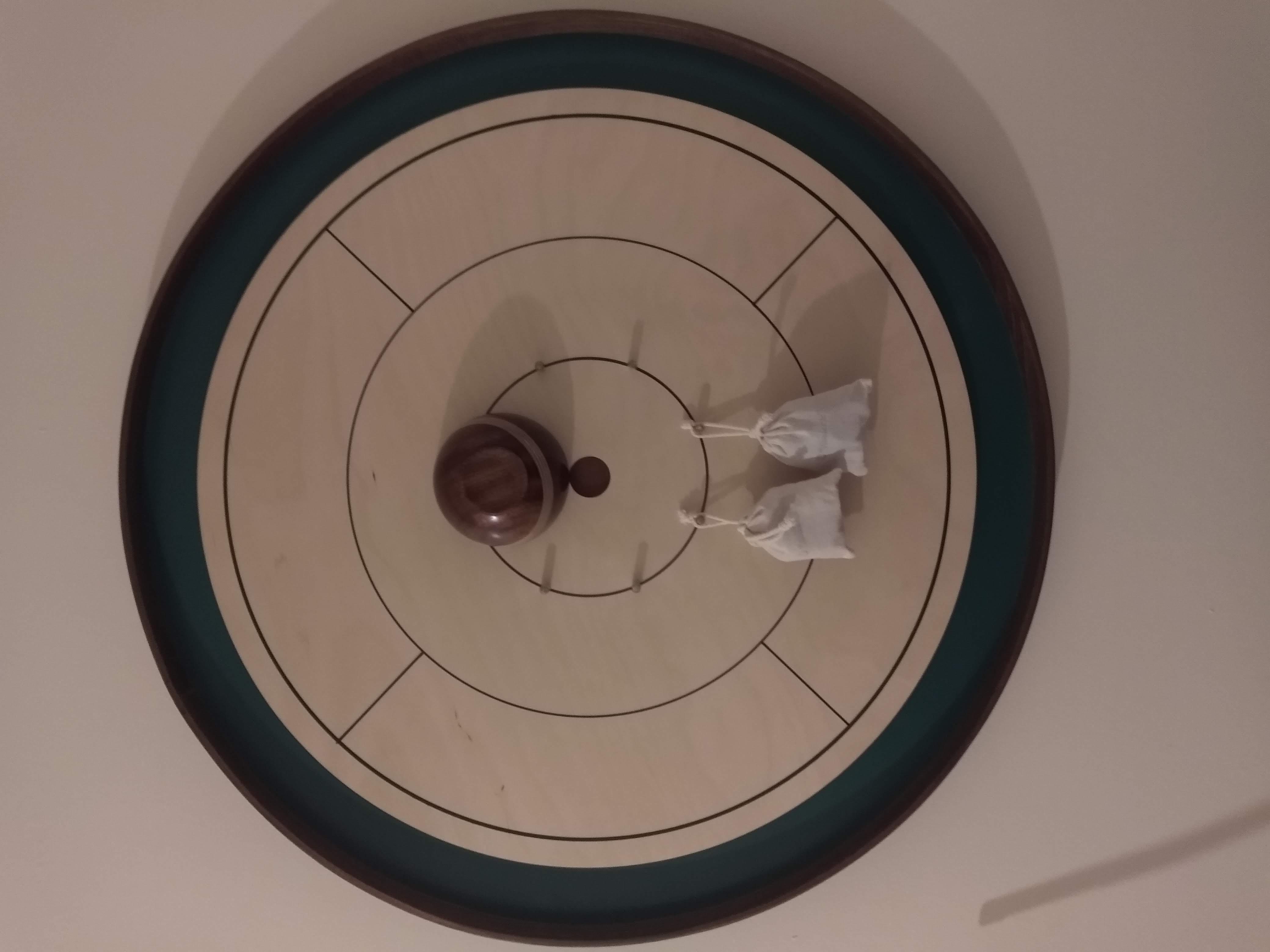
The board plays really well, looks great (in my opinion) and was incredibly fun to make. I am upset about the injury that meant I couldn't see it through to the end but am very grateful to my dad for finishing it for me. The bowl he made is an amazing accompaniment which receives as many (actually more) compliments as the board itself! After showing the board to my family members and several friends after the lockdown eased a bit, not a single person hasn't enjoyed the game (as much as they may dislike losing the game... but that's another matter entirely 😈) which means it's an absolute success!
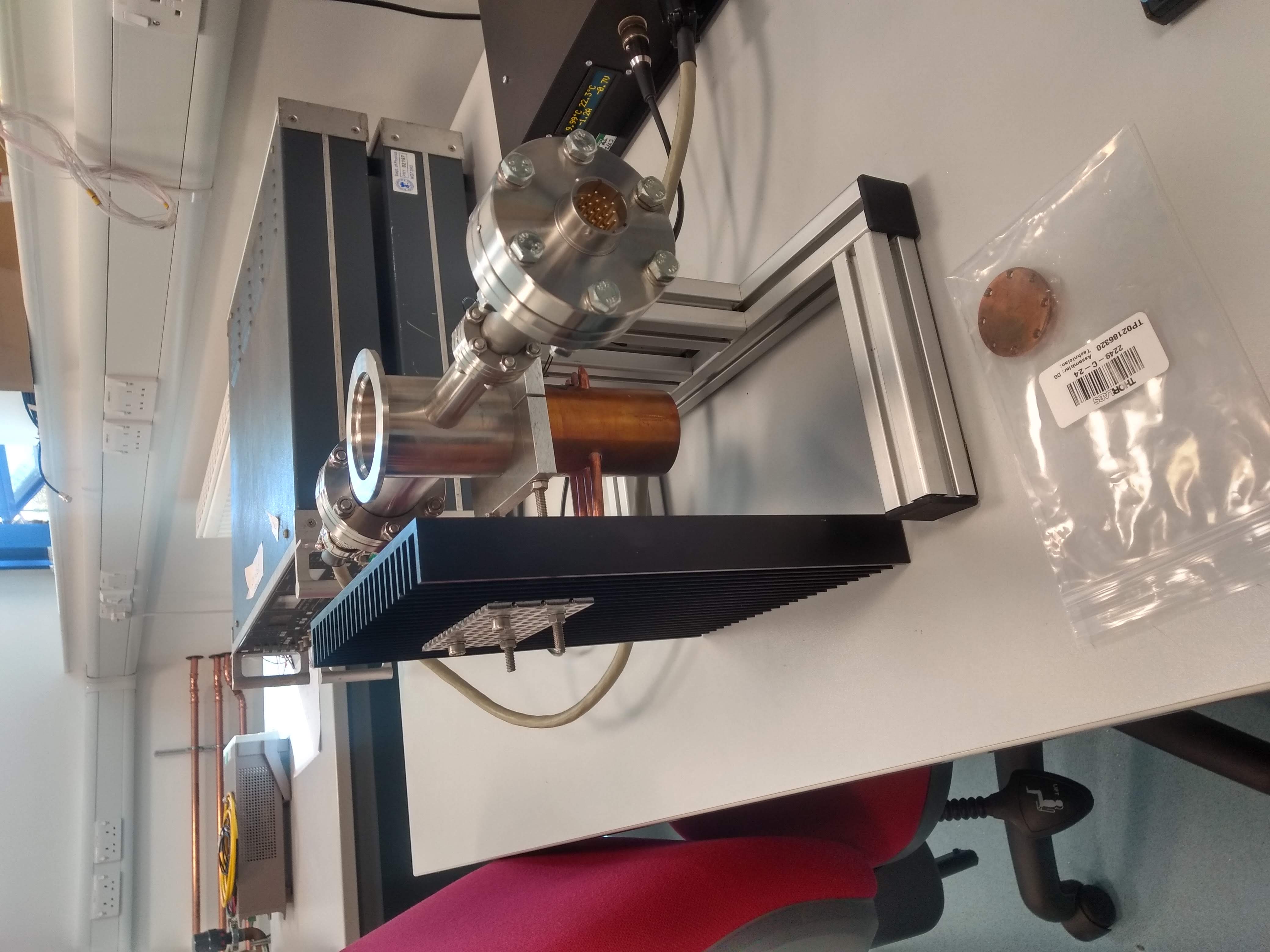
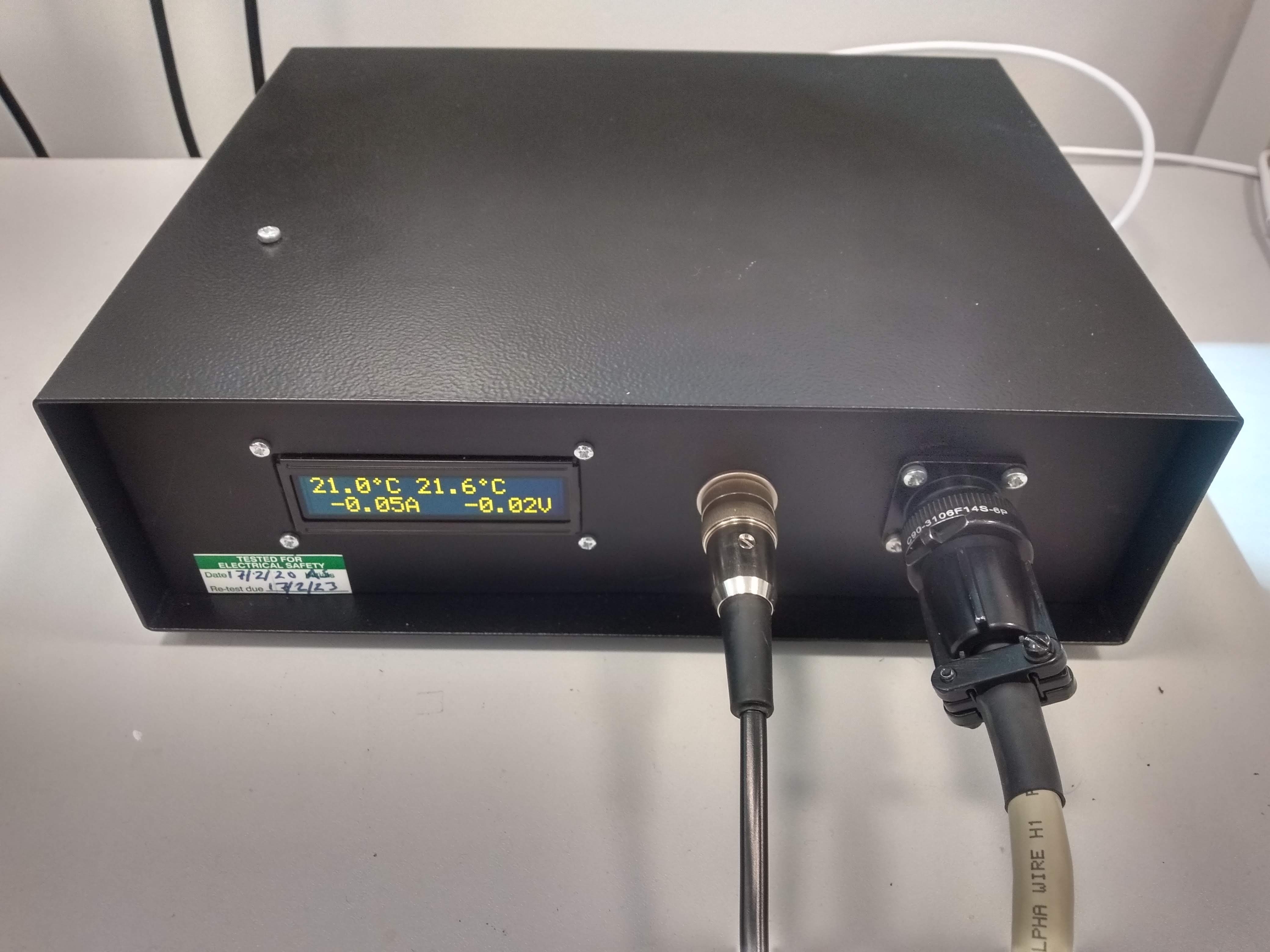
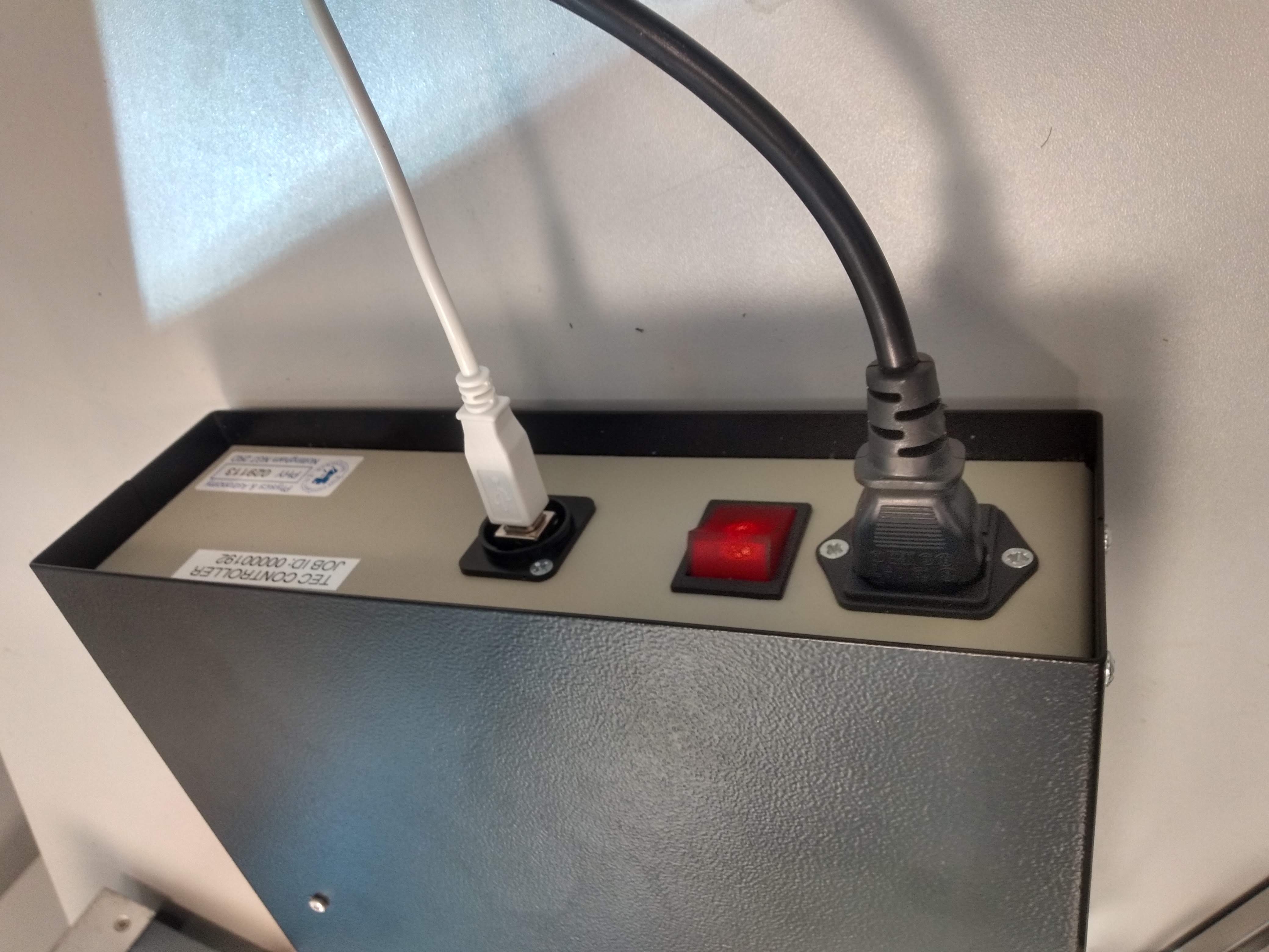
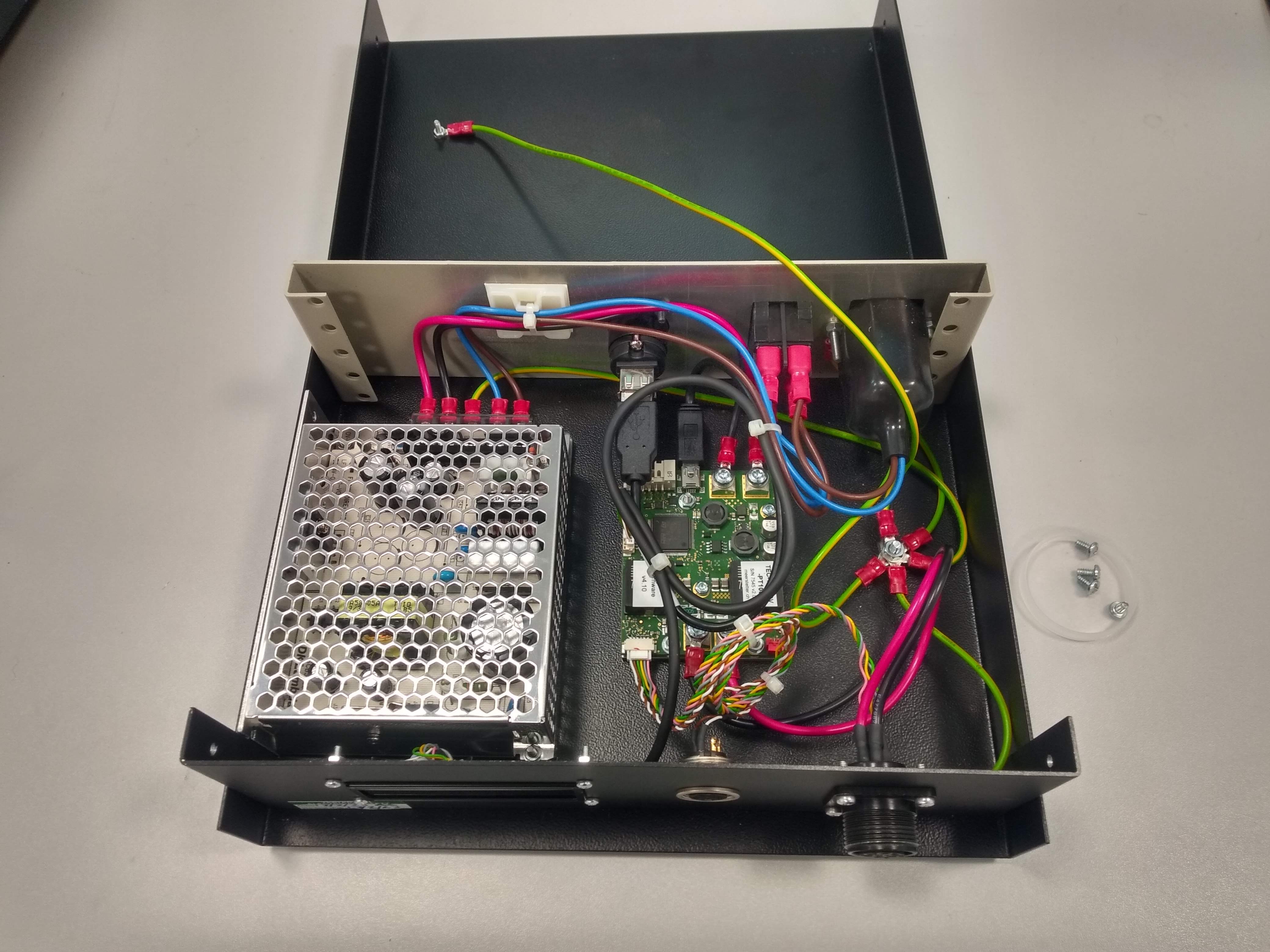
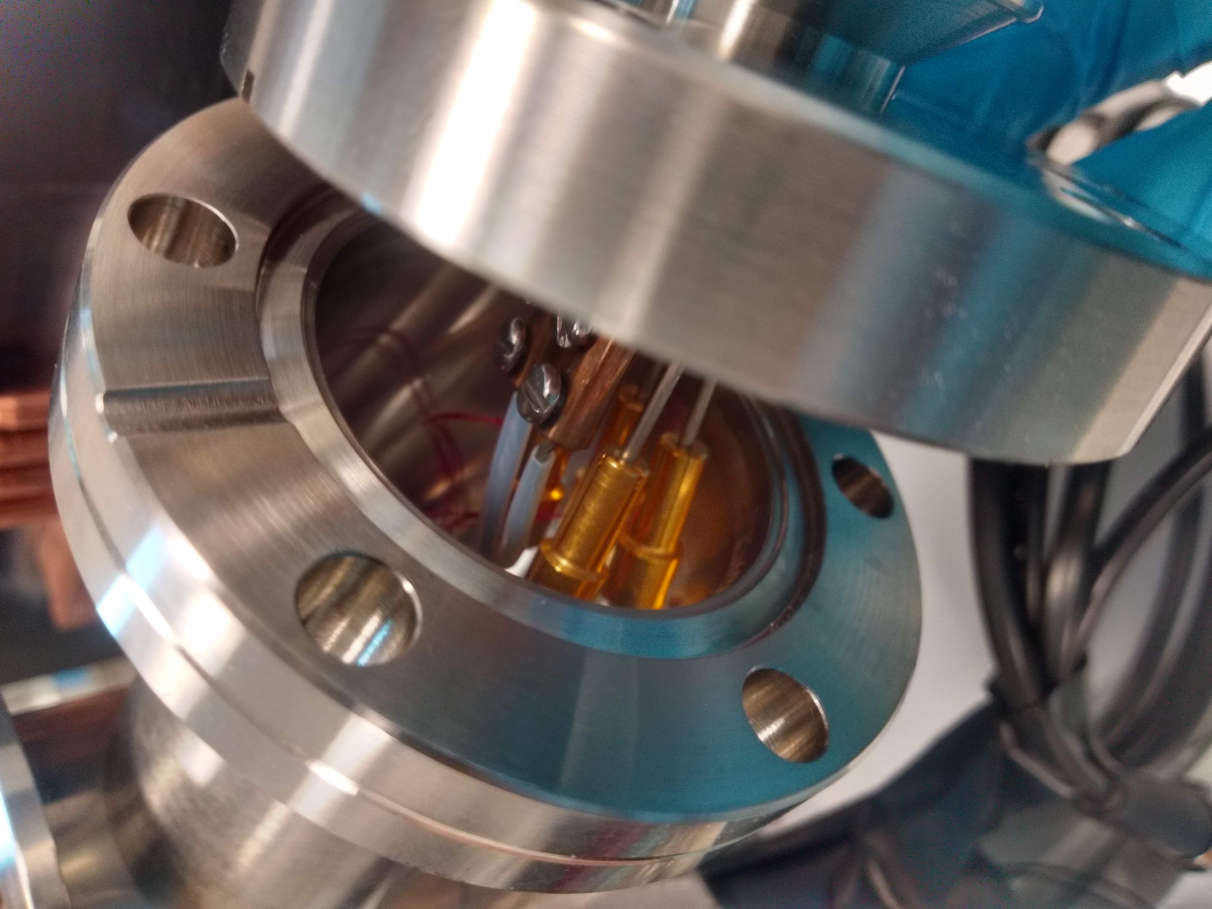
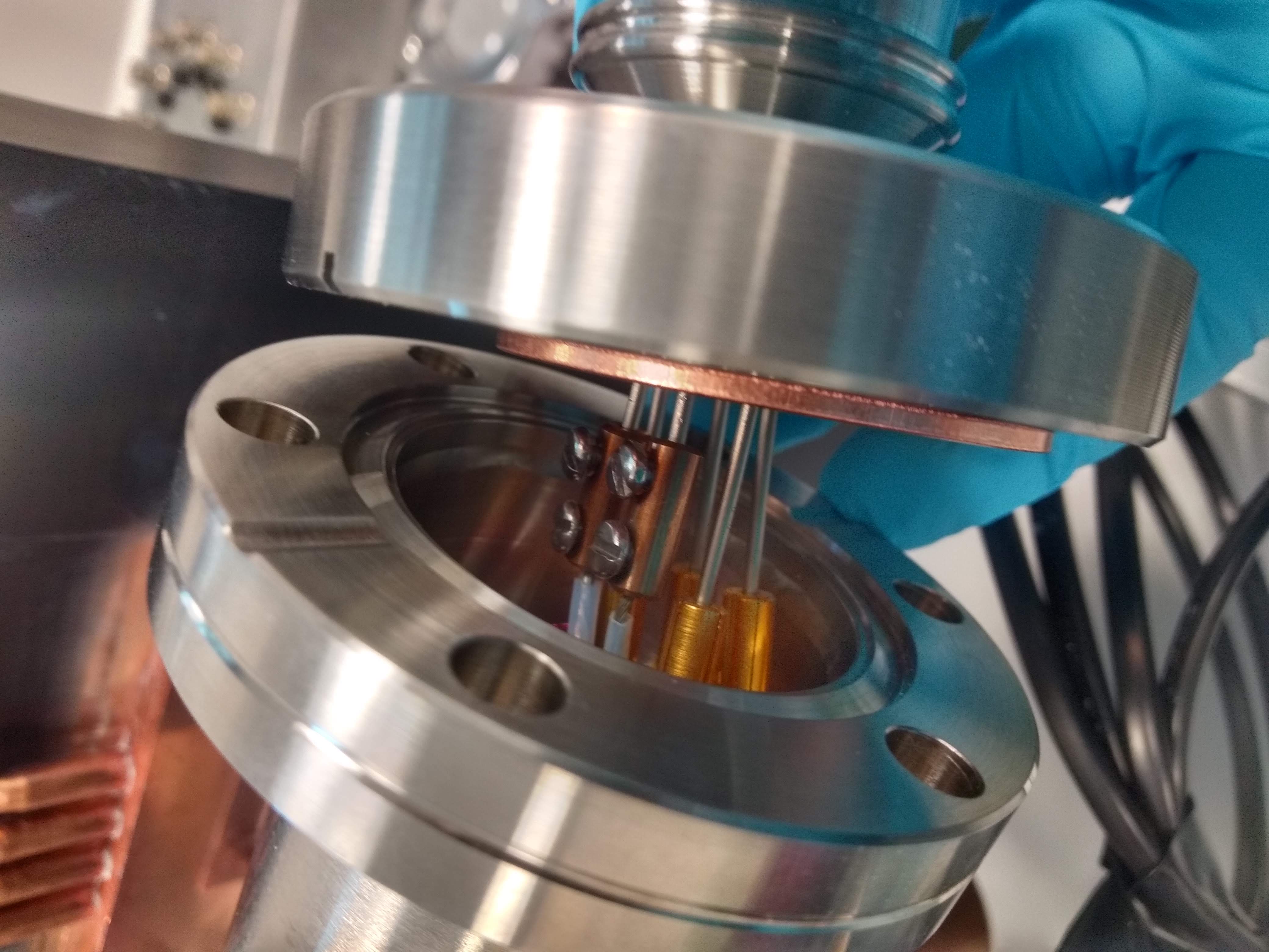
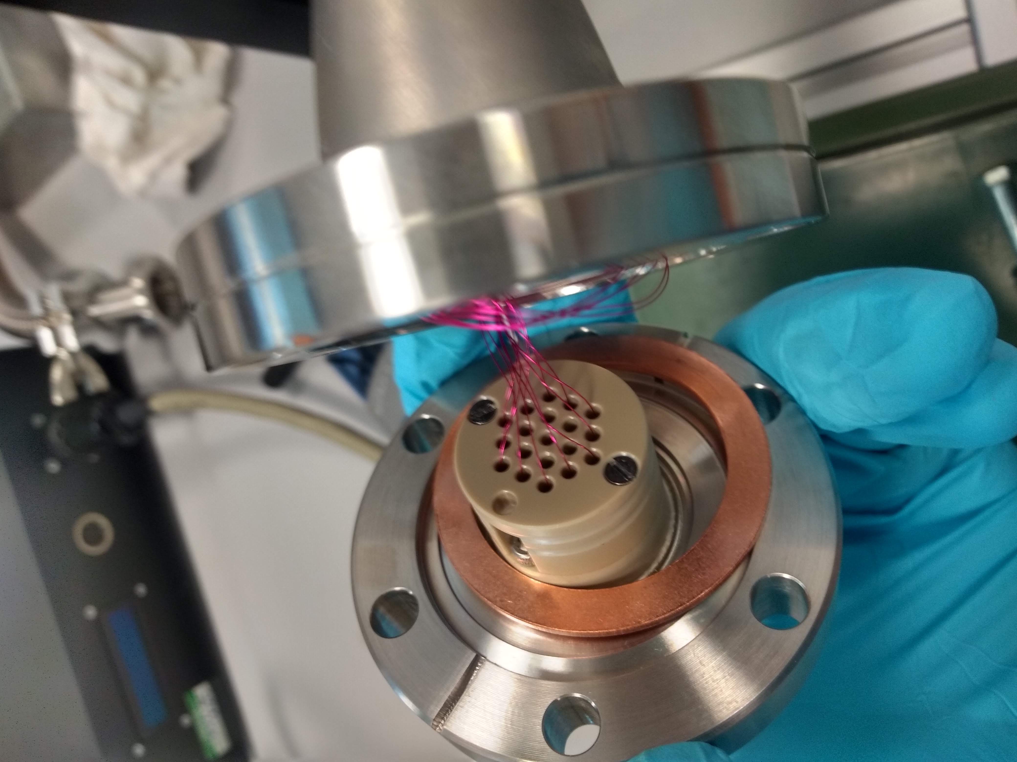
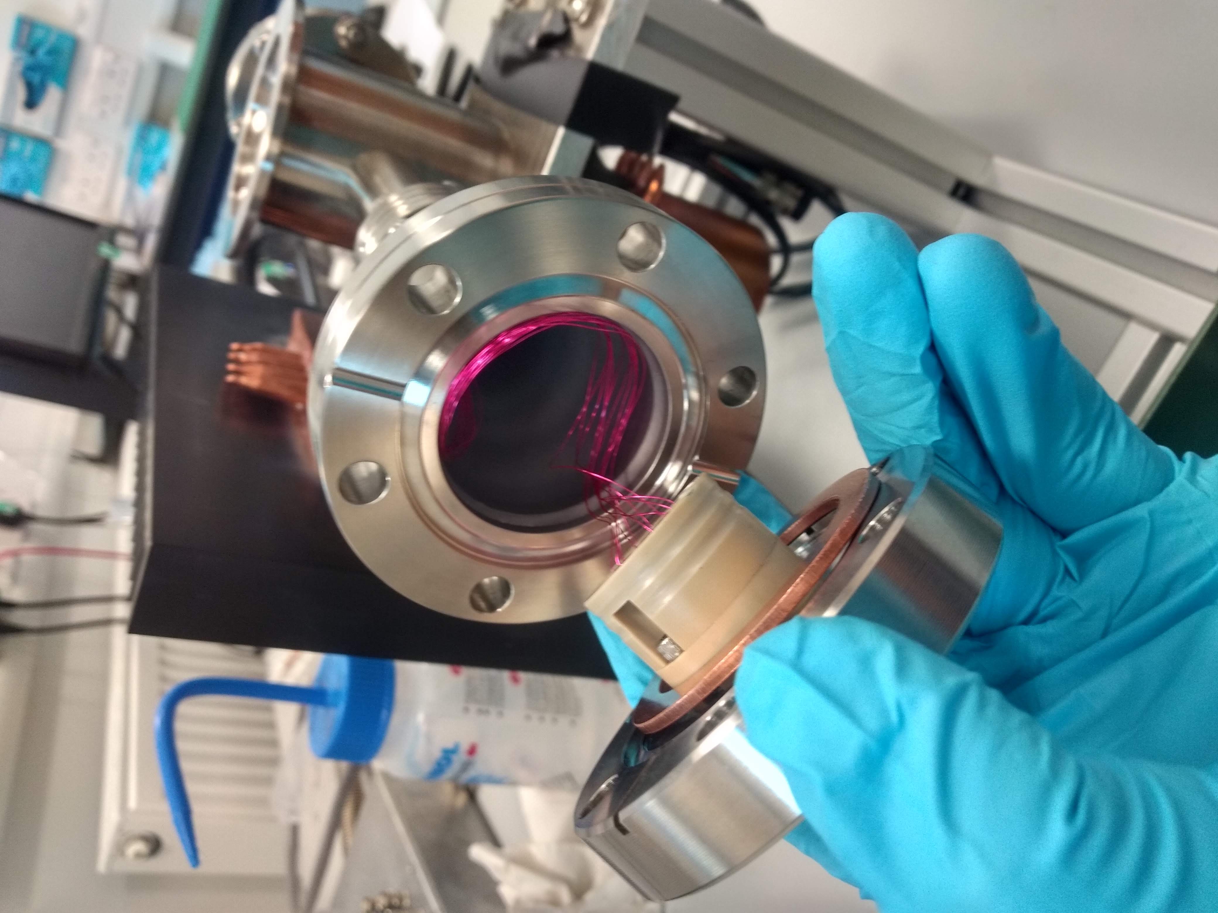
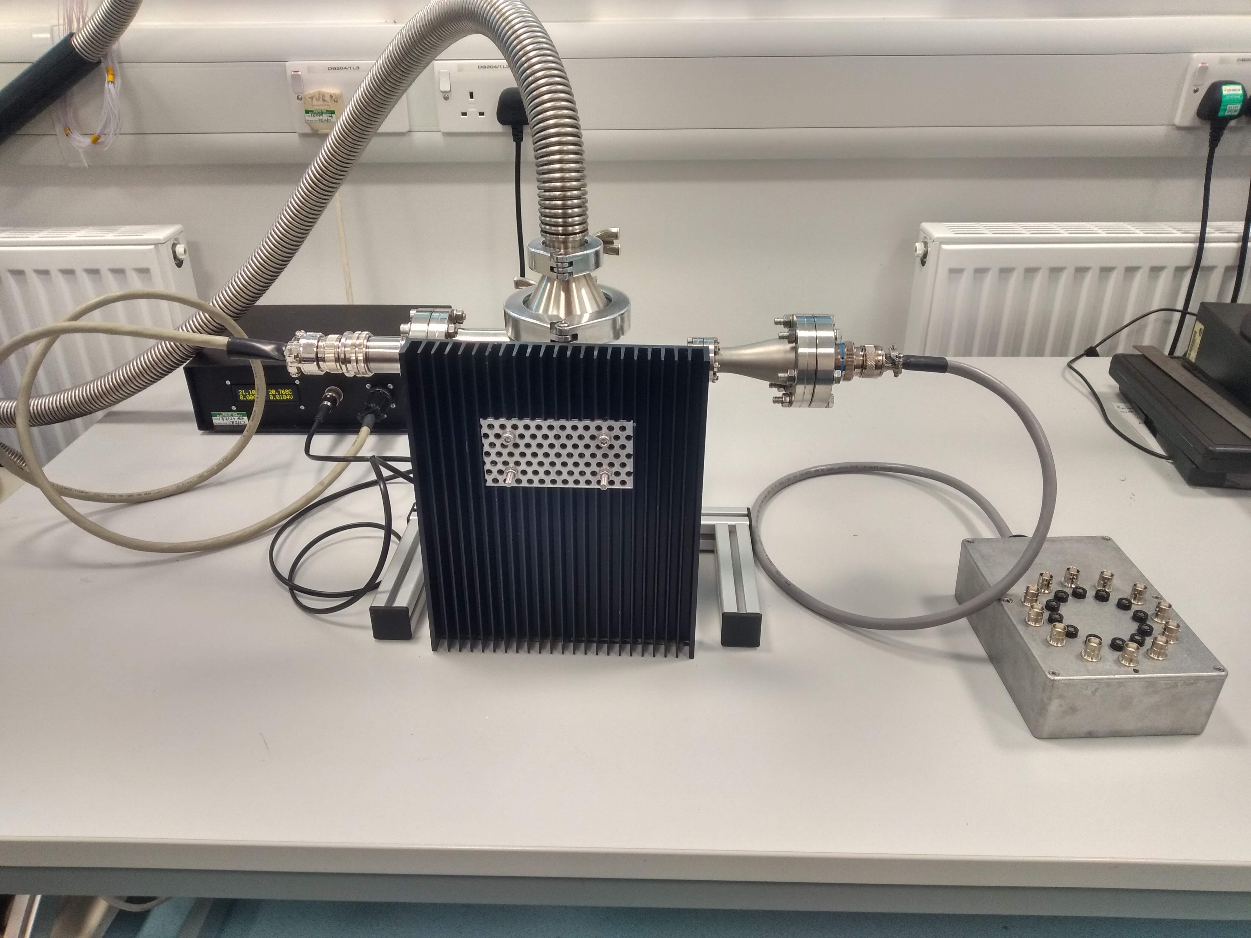
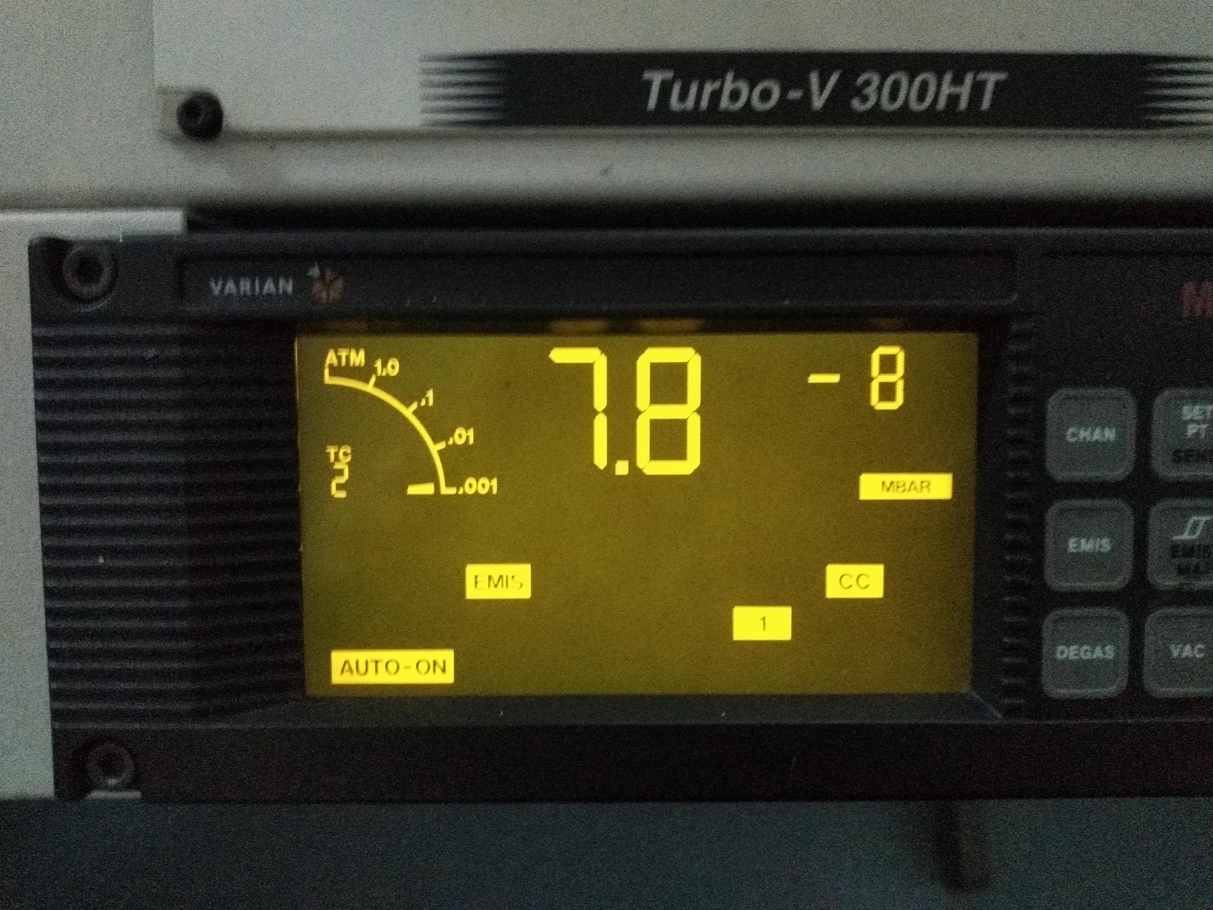
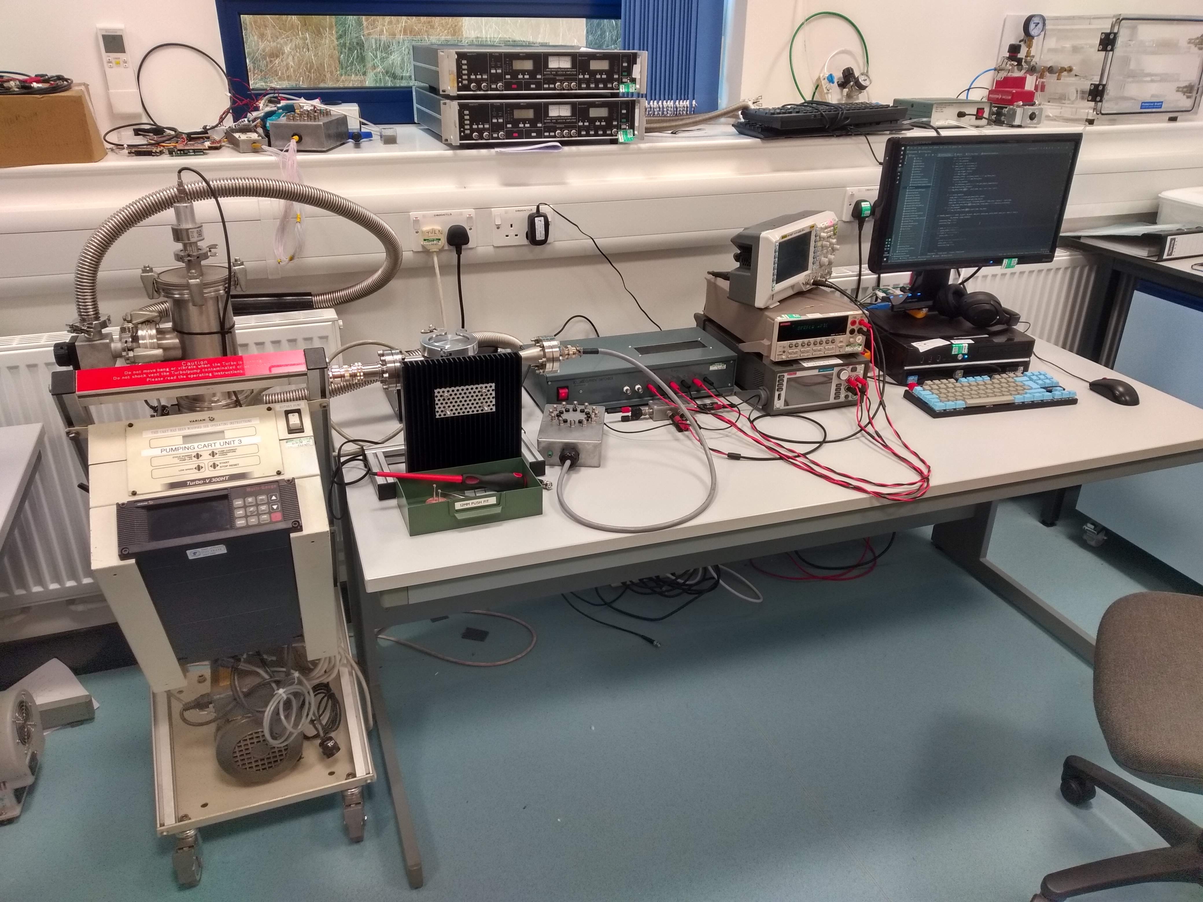
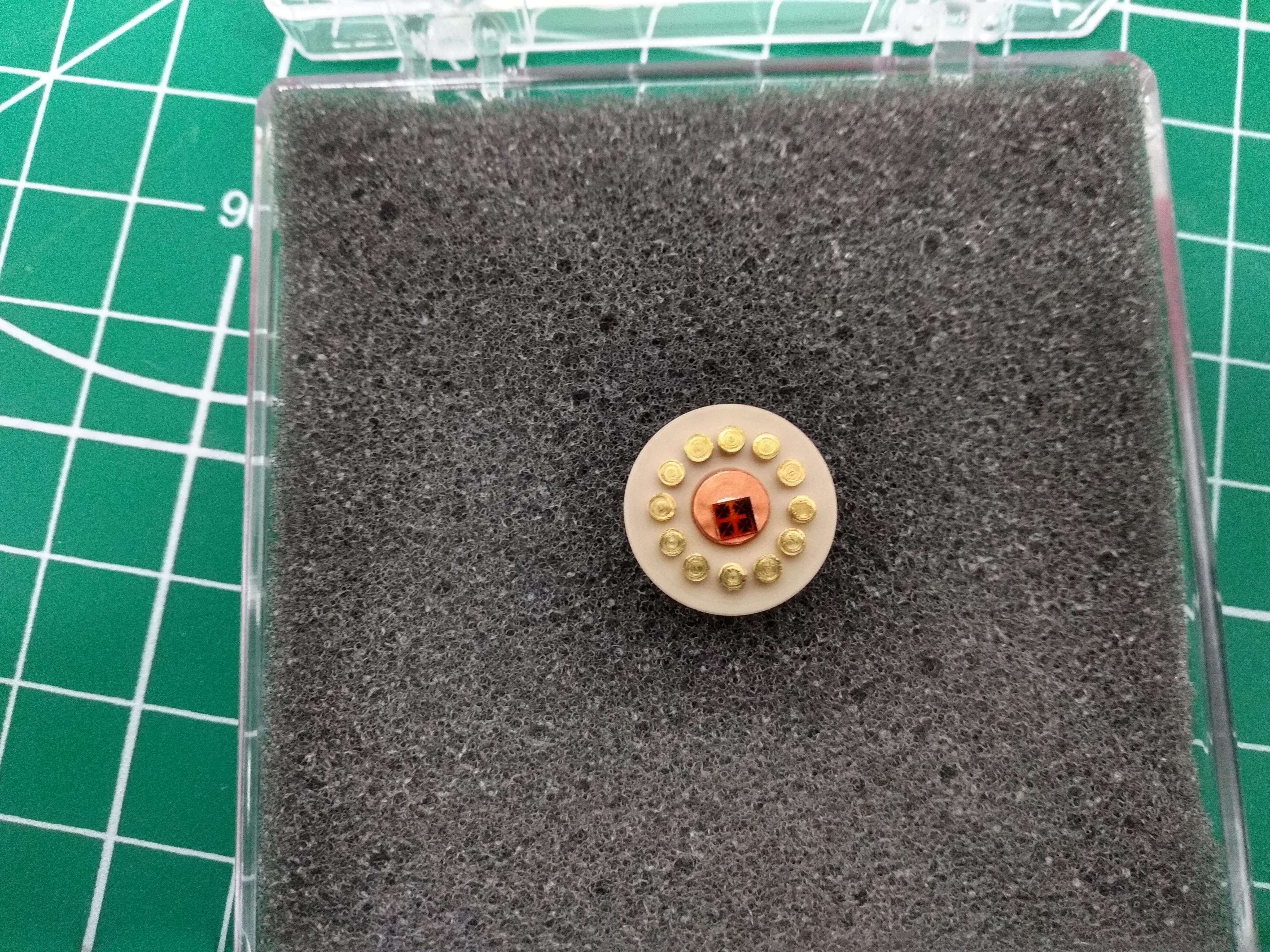
Room Temperature System
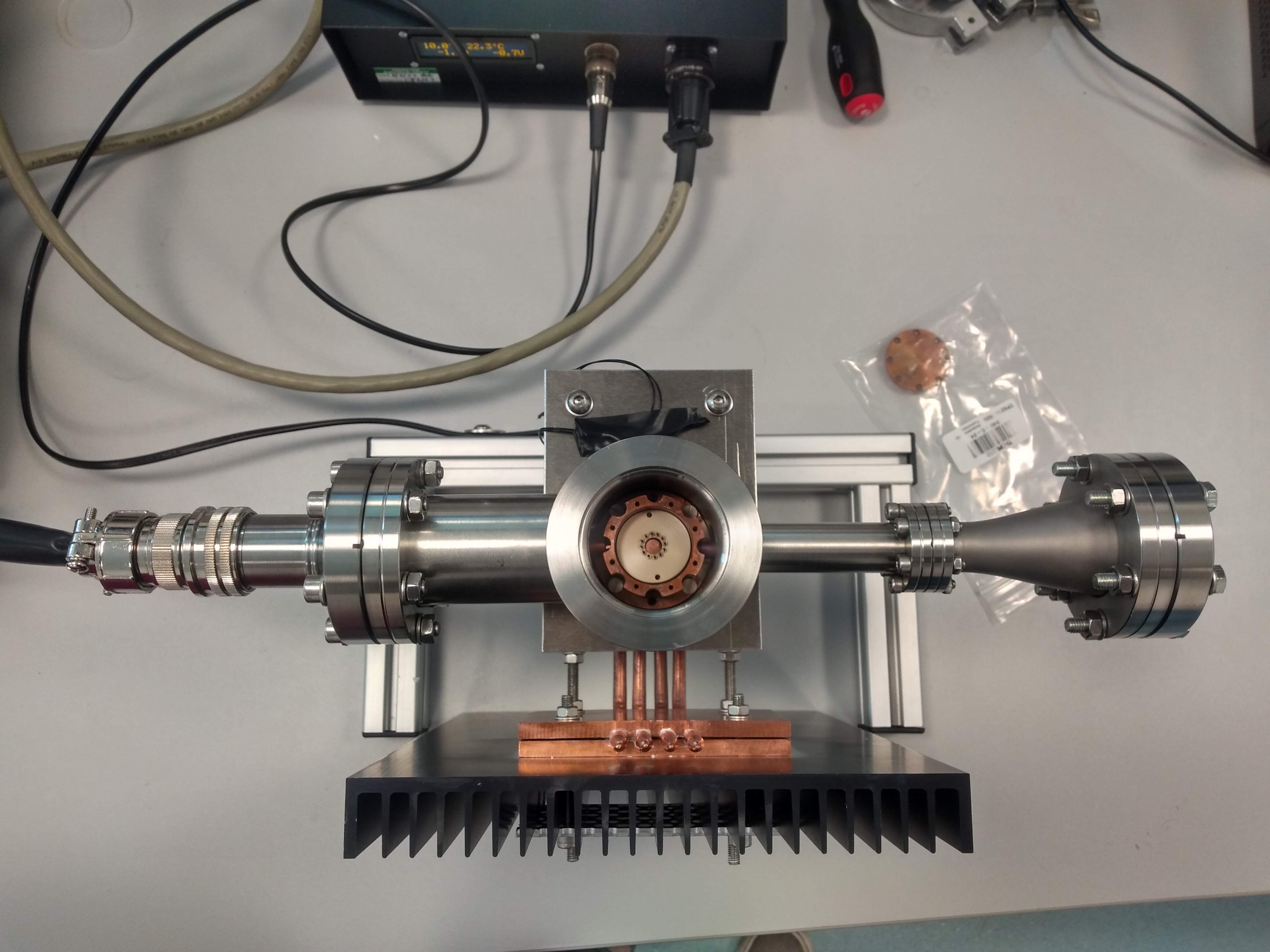
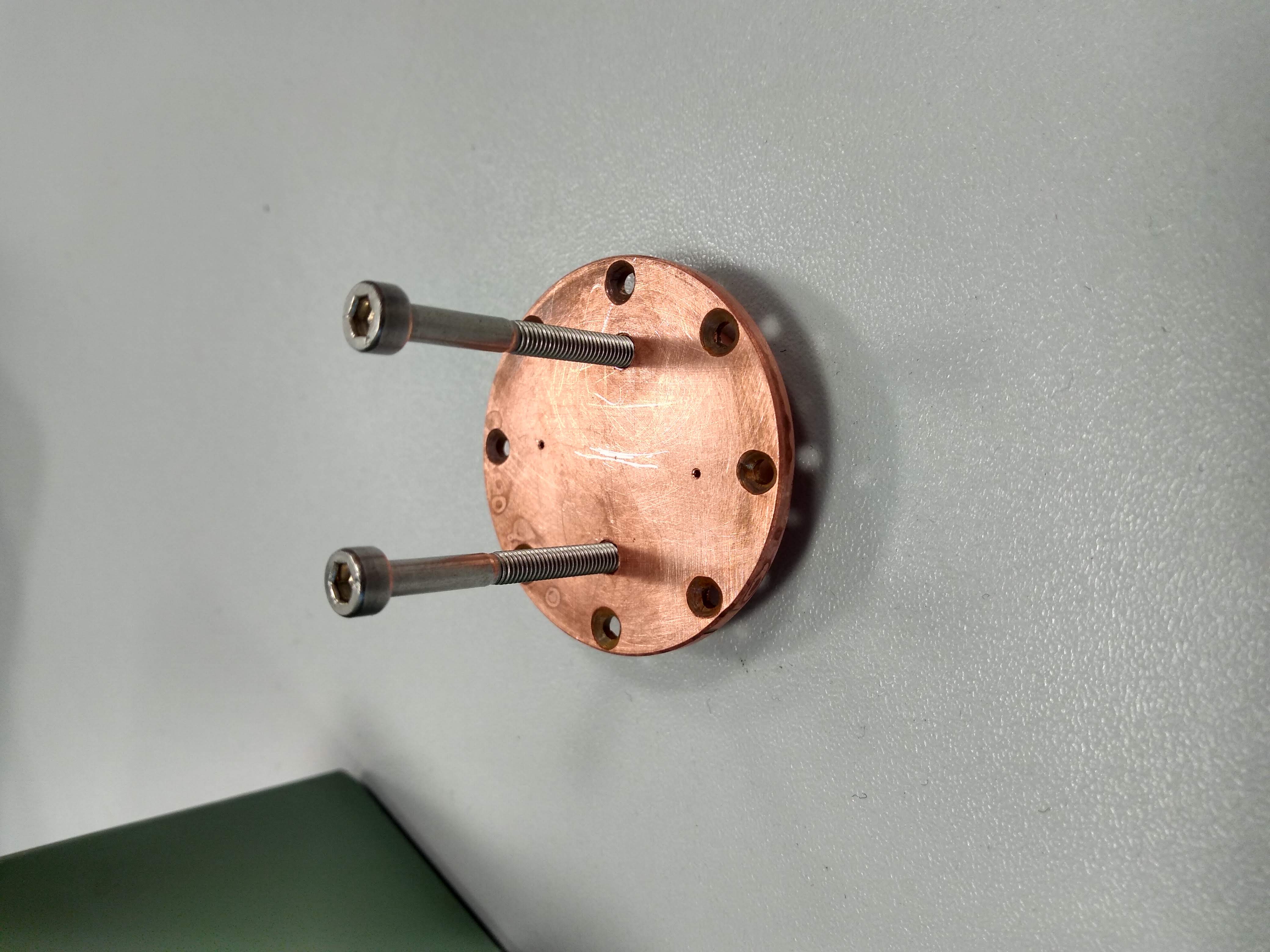
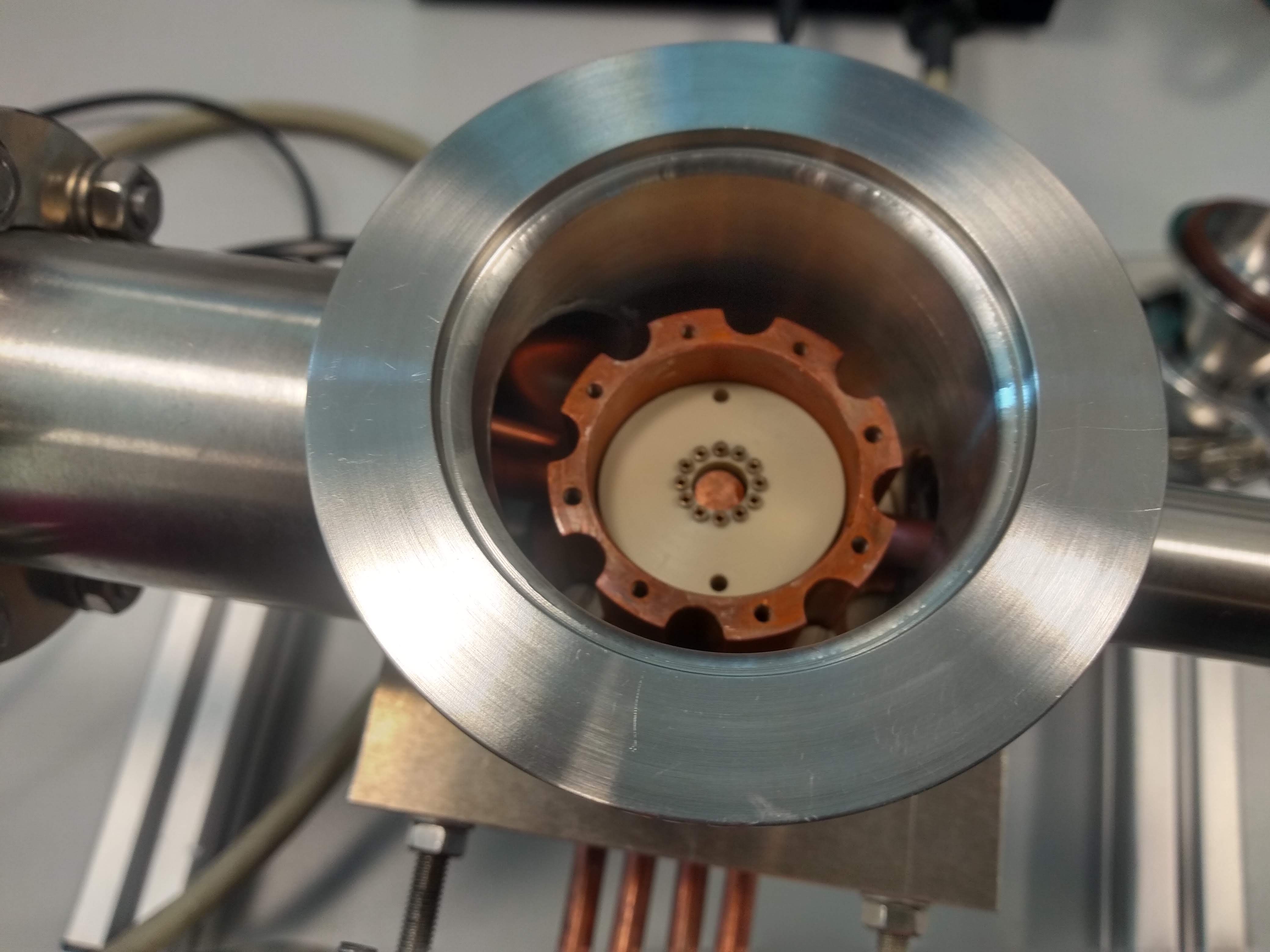
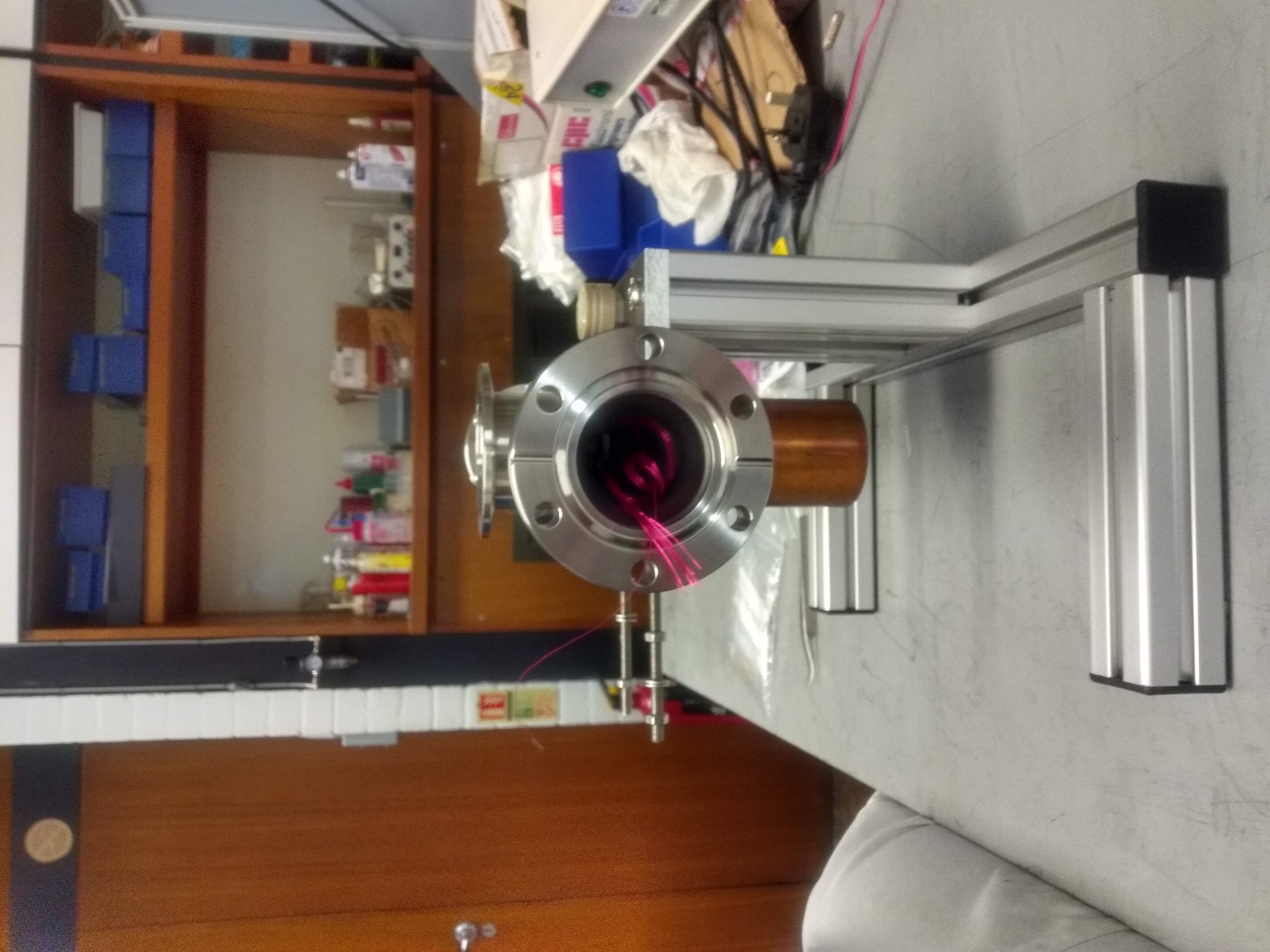
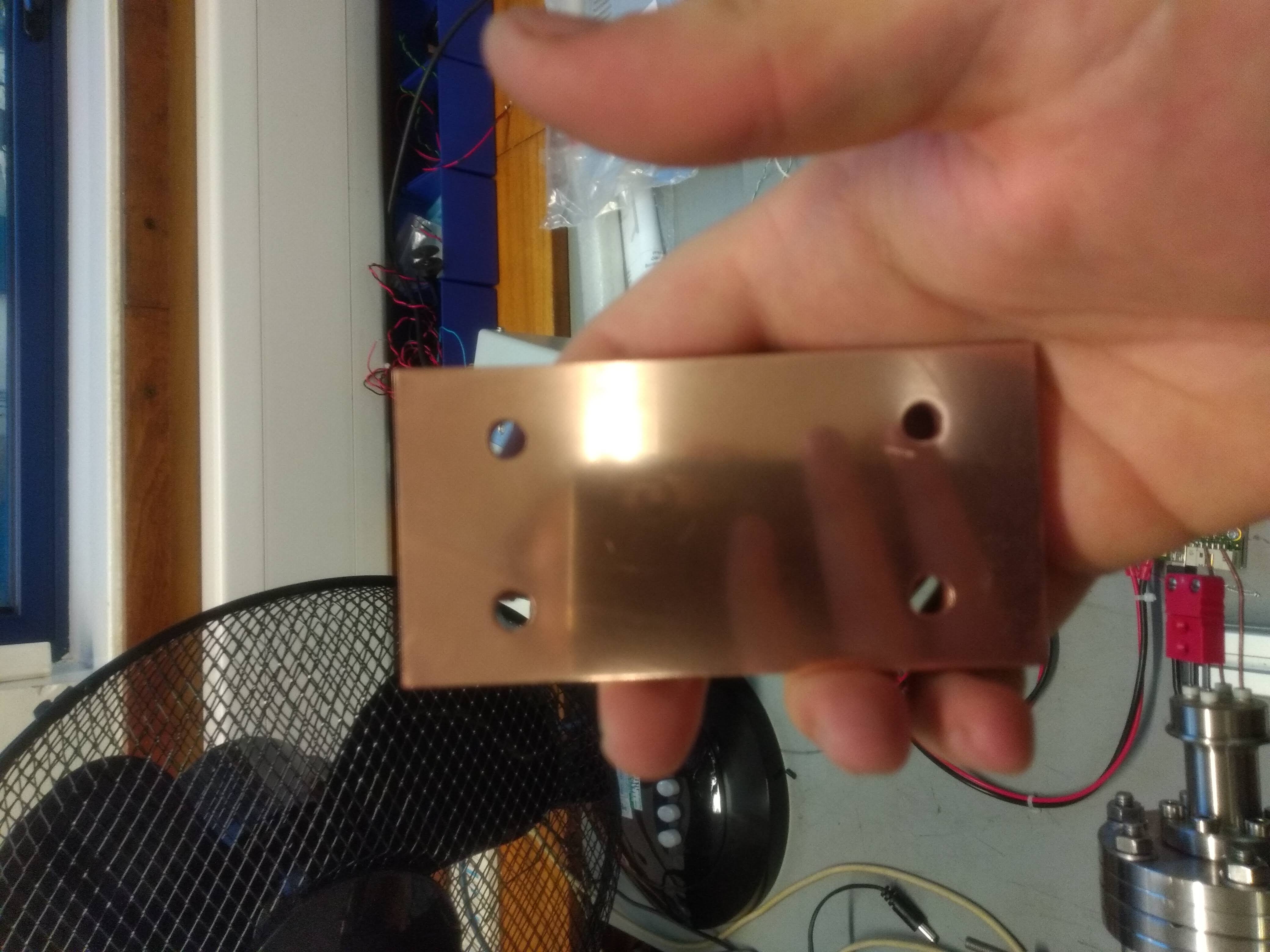
In order to minimise the effect of temperature fluctuations to magneto-resistance measurements, I have devised a room temperature vacuum chamber with accurate Peltier temperature control. Images and further description to come.
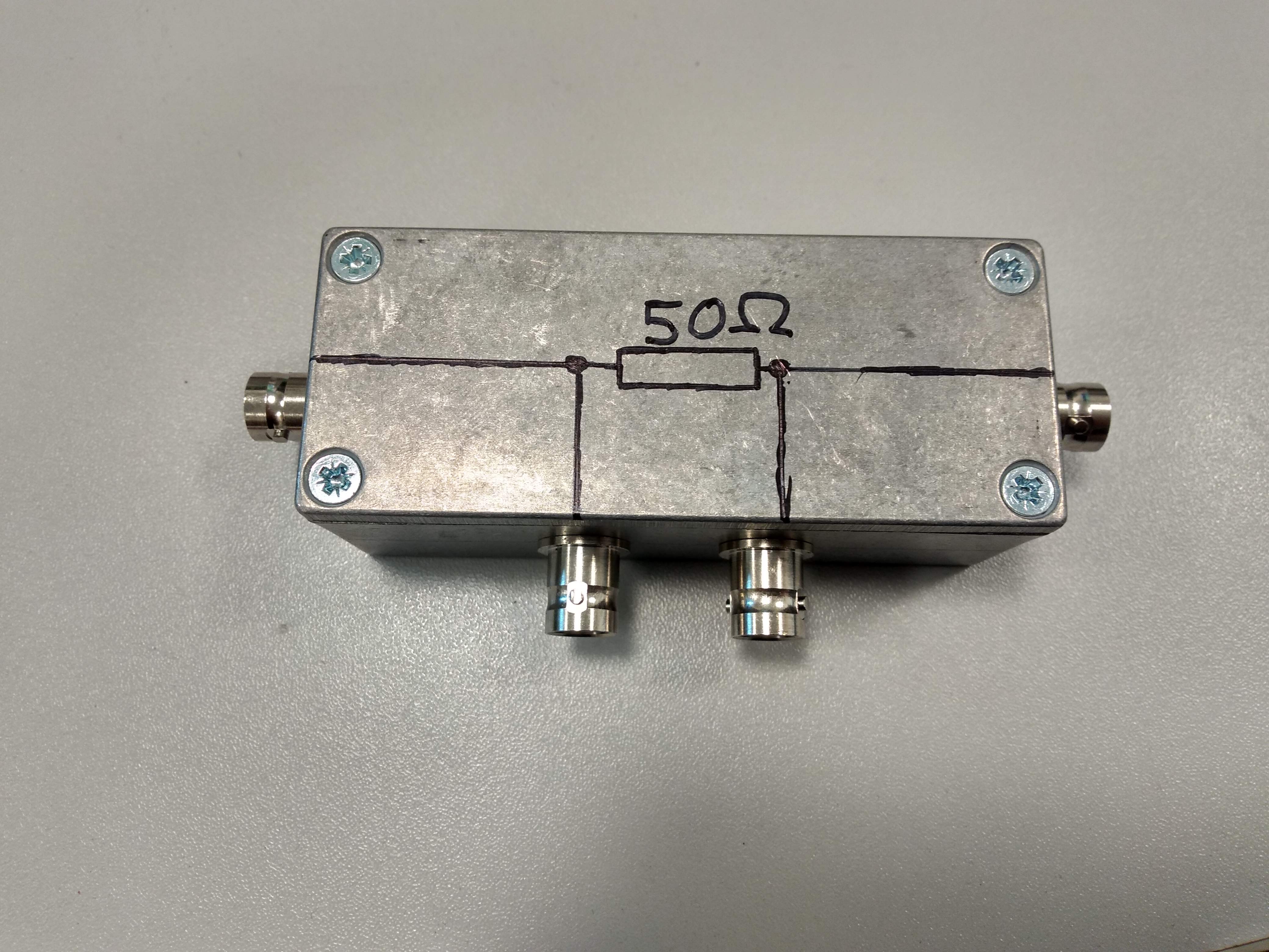
In spintronics, many experiments determine physics properties by measuring resistance changes in a device. For most groups, the devices are tested at cryogenic temperatures because of the low Curie and Néel temperatures of the materials. For the UoN Spintronics group, the devices under question are CuMnAs thin films which are antiferromagnetic at room temperature and so many experiments are done without the aid of cryostats and therefore without temperature control. Typically these devices degrade through oxidation if left in atmosphere. I was tasked with designing a vacuum system with very stable temperature control at around room temperature over the summer between my Masters and PhD. I was given a brief and decided that, for our system and parameters (thermal load etc.), a 20W Peltier device would be more than capable of keeping the device at a stable temperature and just had to design some way to achieve heatsinking while maintaining a vacuum tight seal.
Interactive 8-bit Adder From Discrete Components
 During my 3rd year of studies, my semi-conductor physics lecturer found out I was interested in making a transistor-transistor logic (TTL) circuit and together we came up with the idea to make an 8-bit adder using discrete transistors with LEDs to demonstrate the adding mechanism in TTL. The outline of the project is this: make an interactive display piece for outreach which should demonstrate transistor logic and show how much transistors have shrunk since their invention. The piece should teach about computing at a simple level including giving reason to learn about binary. In order to do this, I first drew a logic gate circuit and then learned how to make each gate using npn bipolar transistors. Once complete, I drew the full circuit diagram and added LEDs to show the logic level at certain points.
My first attempt at the full adder circuit was a failure. I did not realise that the diode drop across the NPNs would be so large and so learned why all logic is typically inverted, the hard way. The signals would always be too weak to light an LED after two or three gates. It turns out that inverting all logic gives 5V off the top of the gate whenever it is not open and then 0V when the gate is open. Using the 5V for inputs to other gates, and for LEDs, is a must. Using this new knowledge, and the added money of the outreach budget, the project has taken a turn towards professionally produced PCBs instead of strip board.
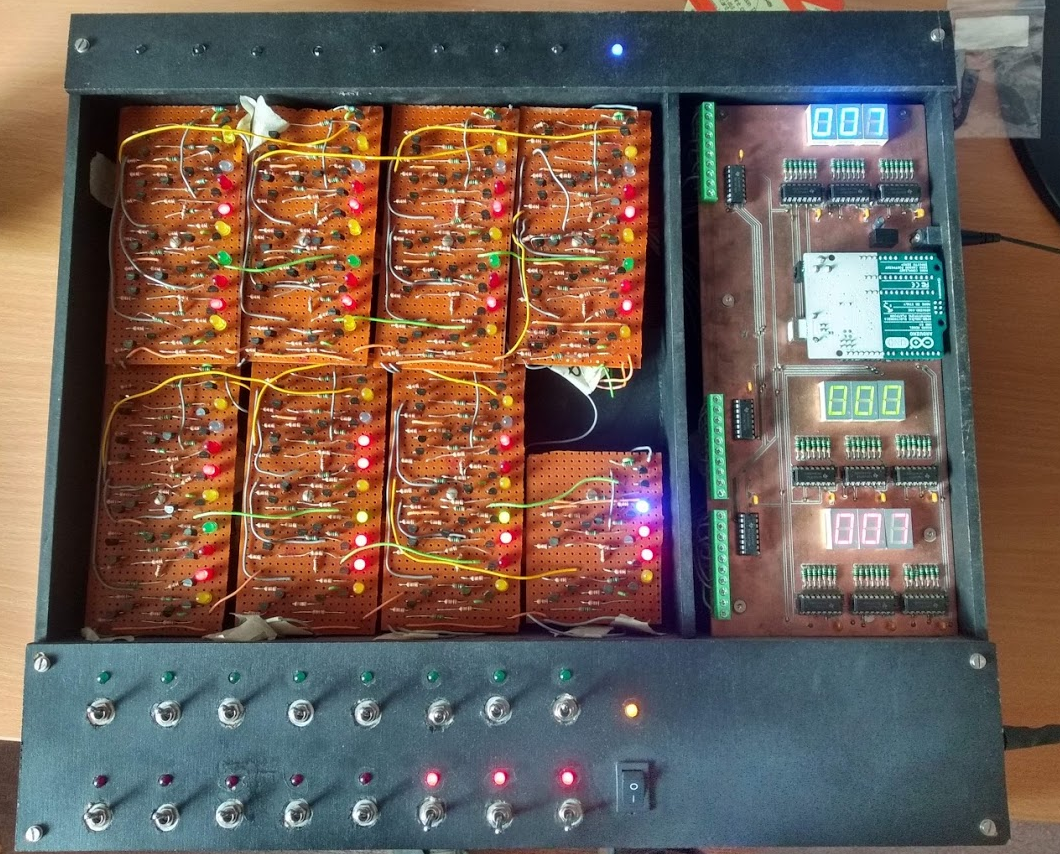
The display board uses an Arduino Uno to convert the binary values from each input and output to each adder circuit to convert binary to human readable decimal. This board works flawlessly and contains a 12V regulator. Despite working, the separate power supply and the piece requiring two power supplies, has led us to redesign this, using the same pieces but including a built in power supply to provide both +12V and +5V rails for the Arduino and adder boards respectively. This working board and not working adder circuits can be seen on the right.
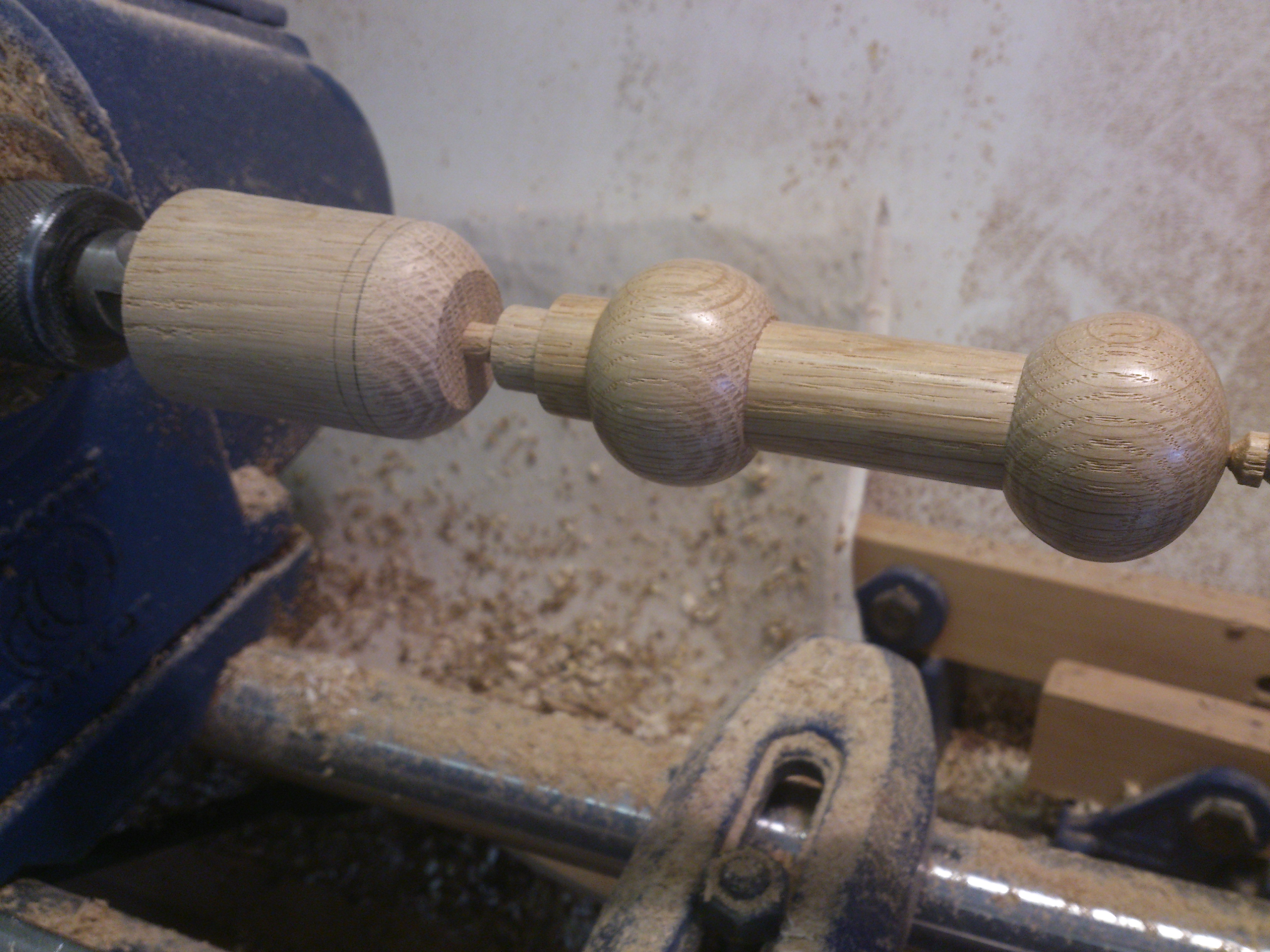
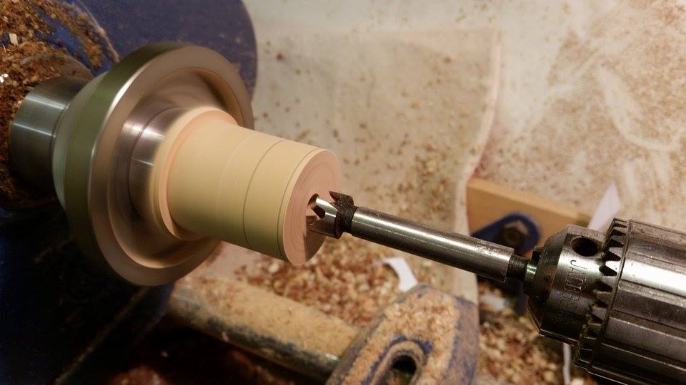
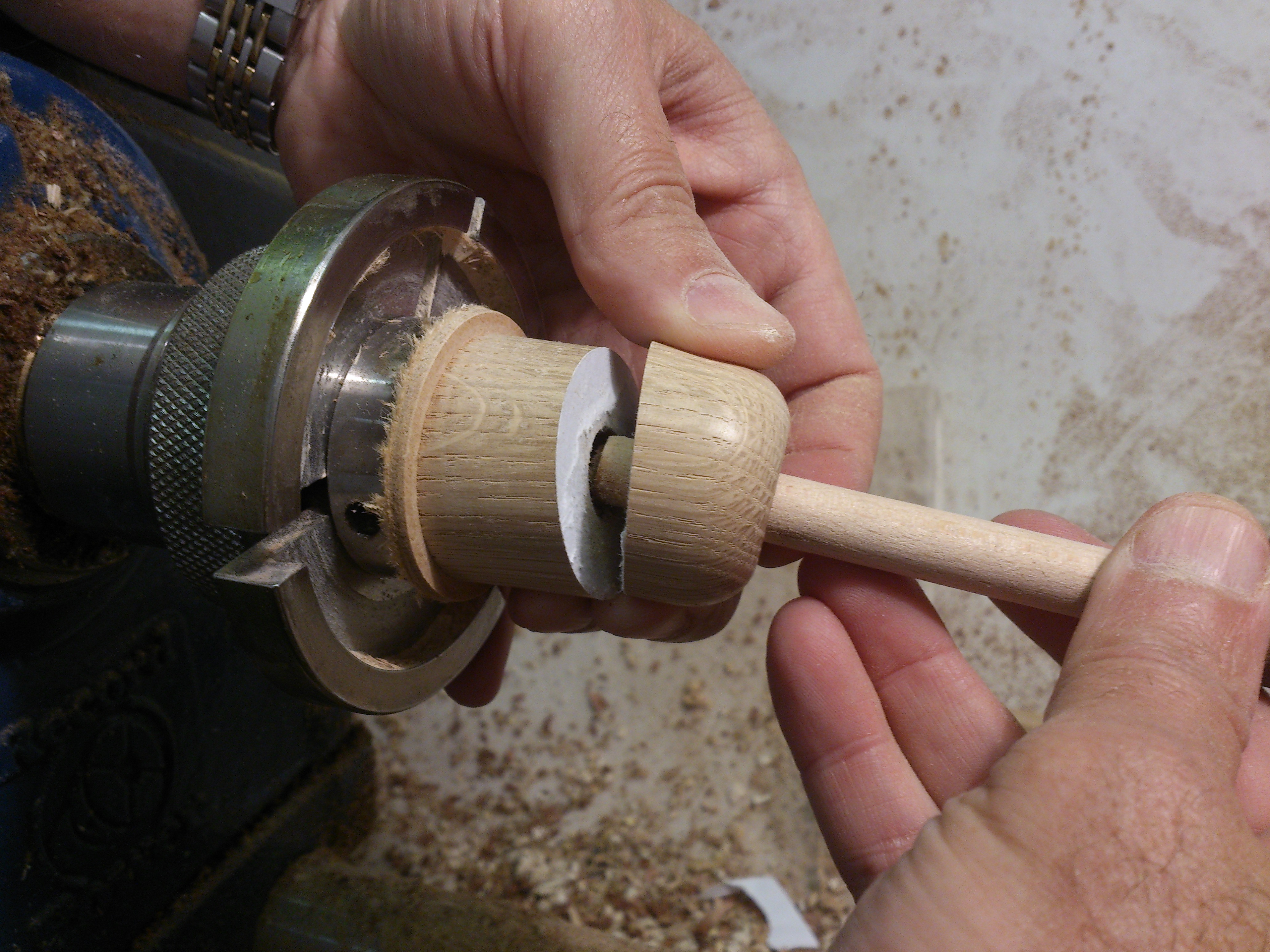
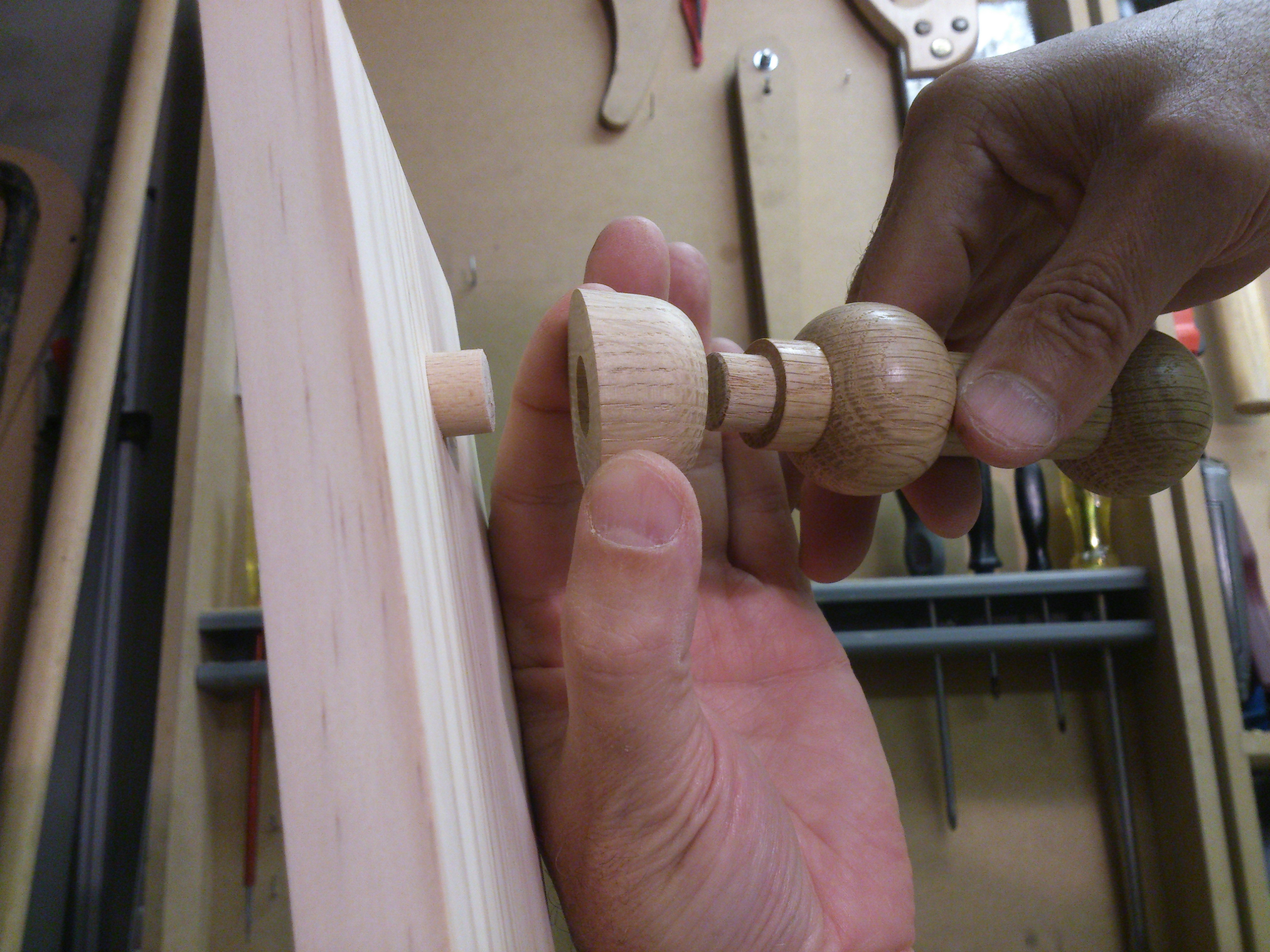
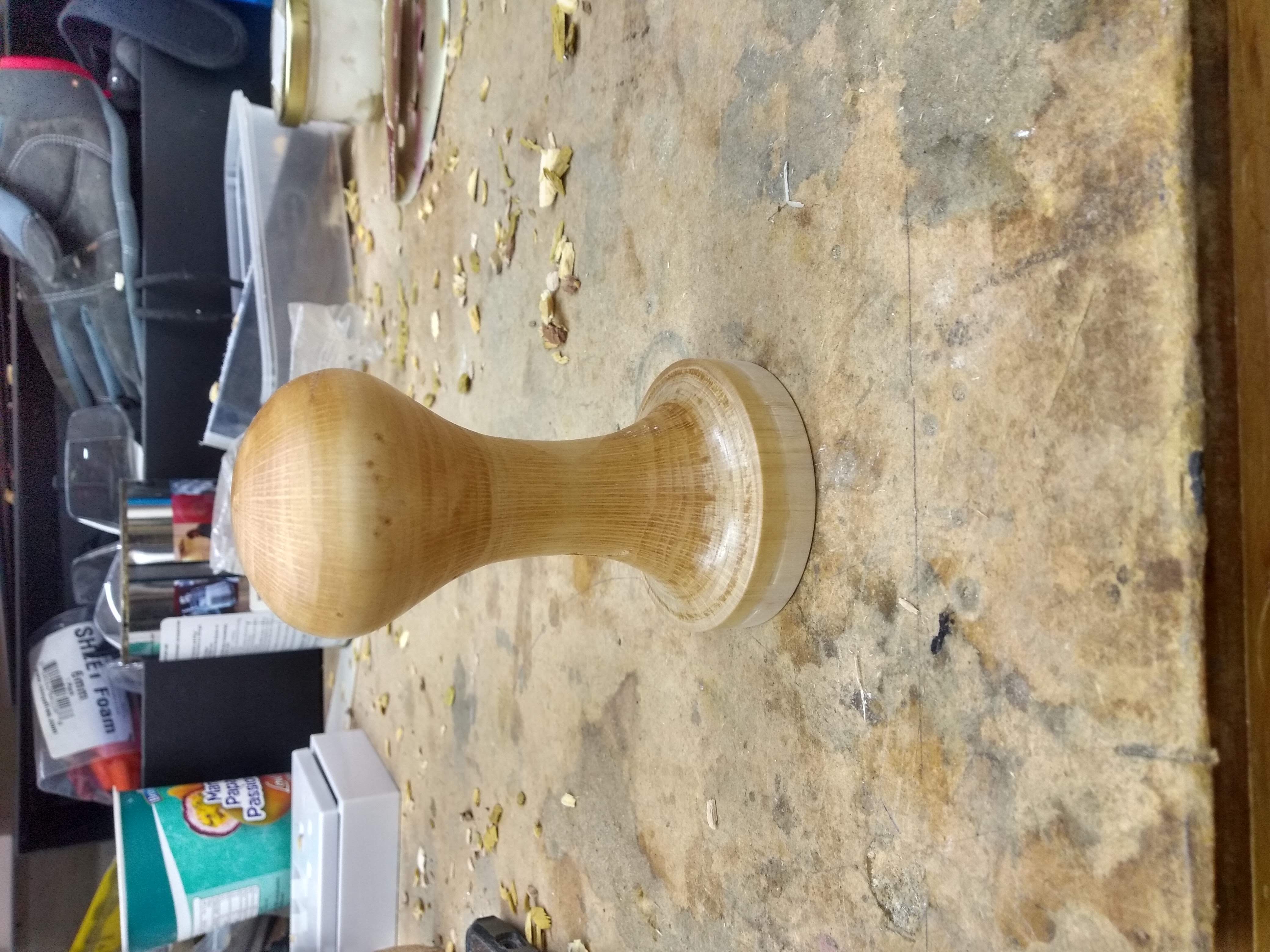
Peripheral Rack
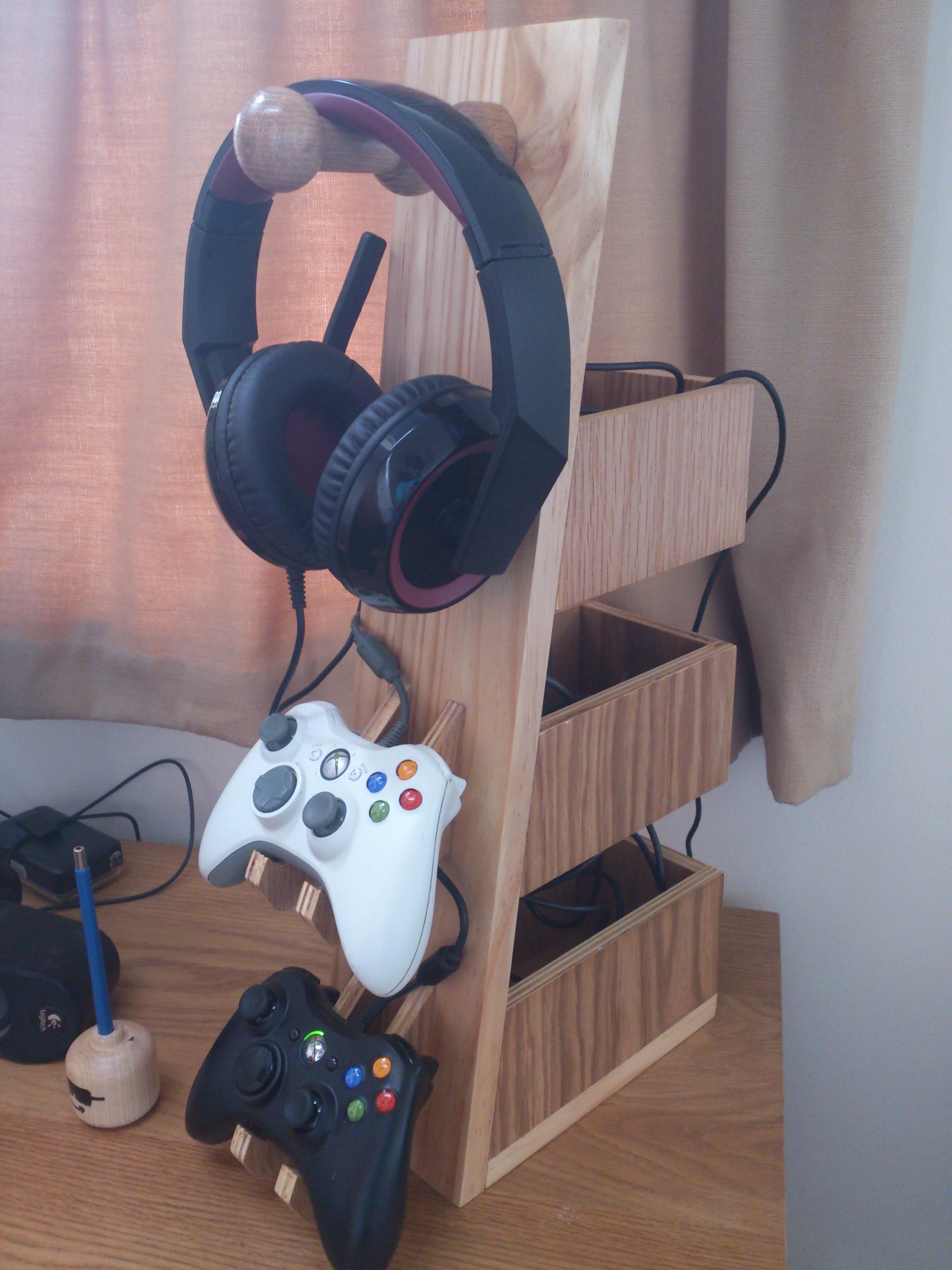
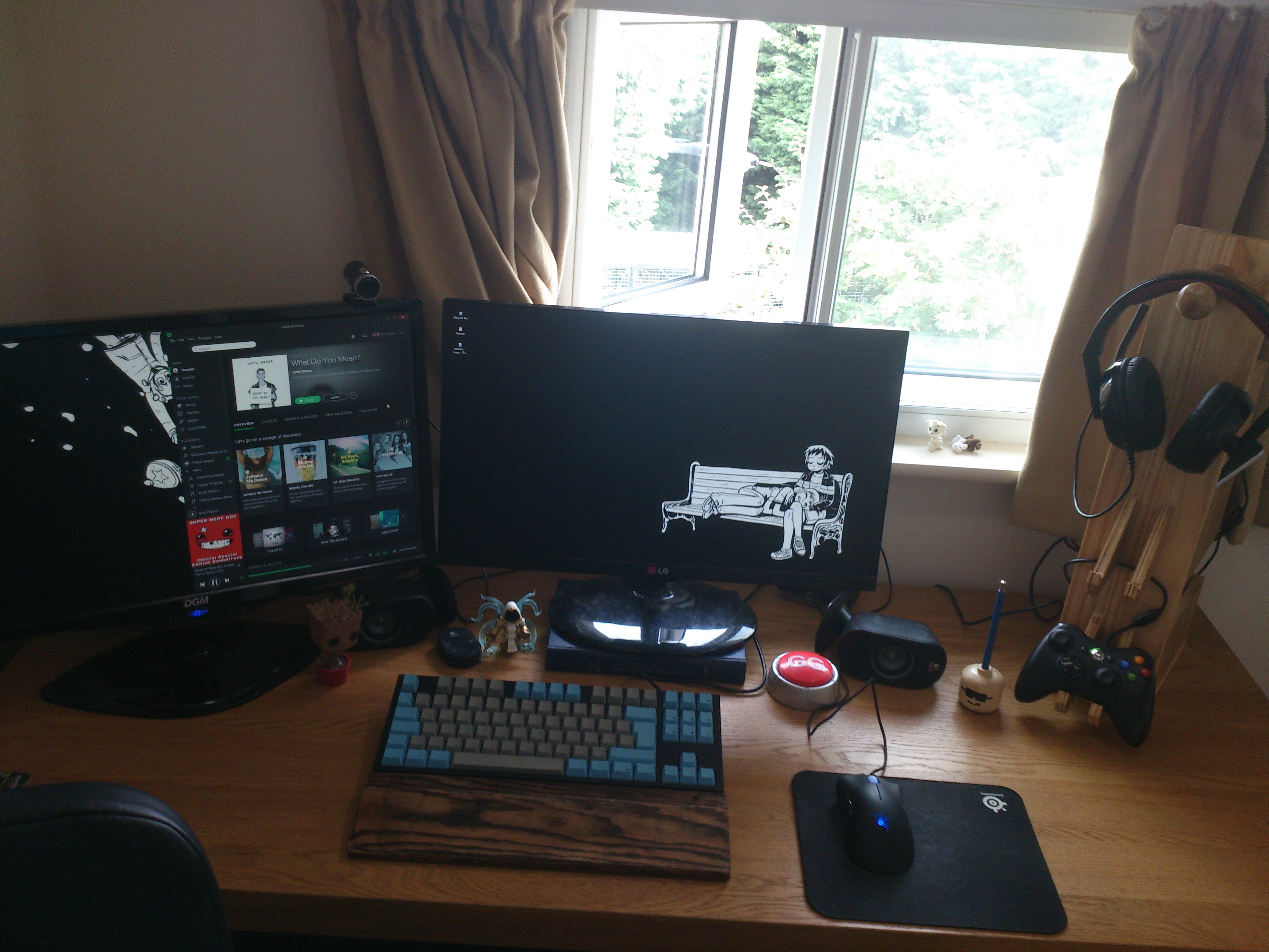
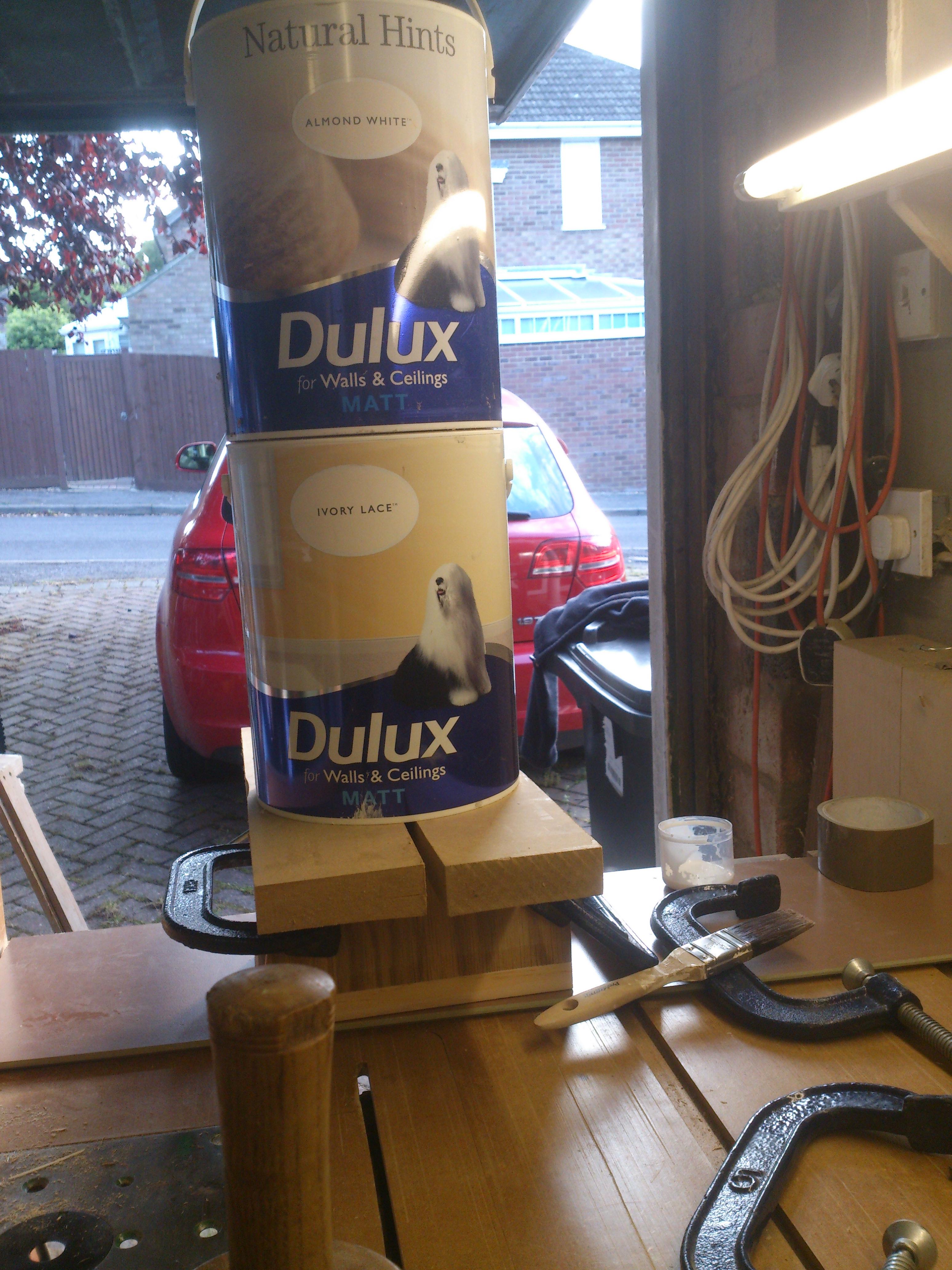
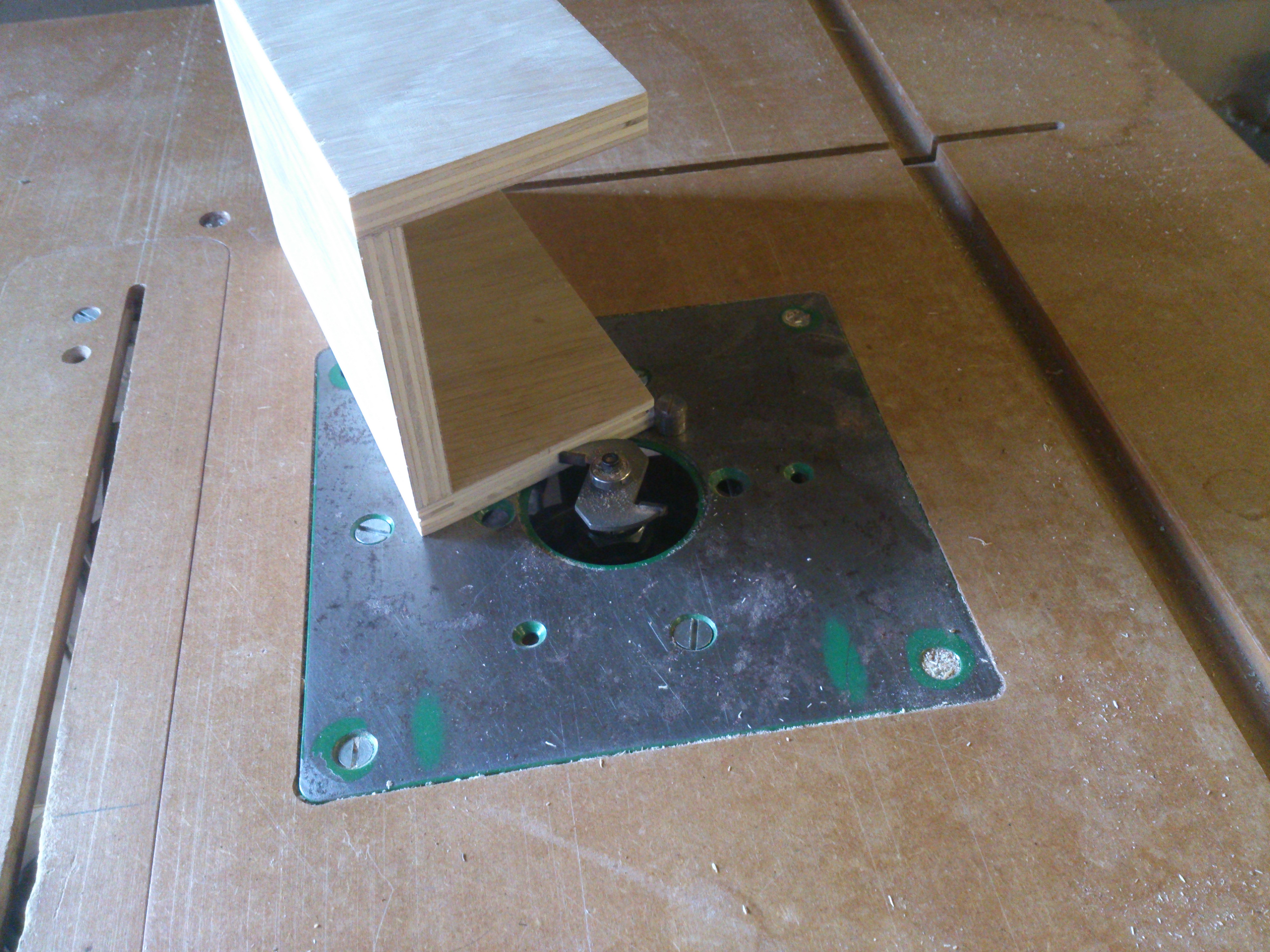
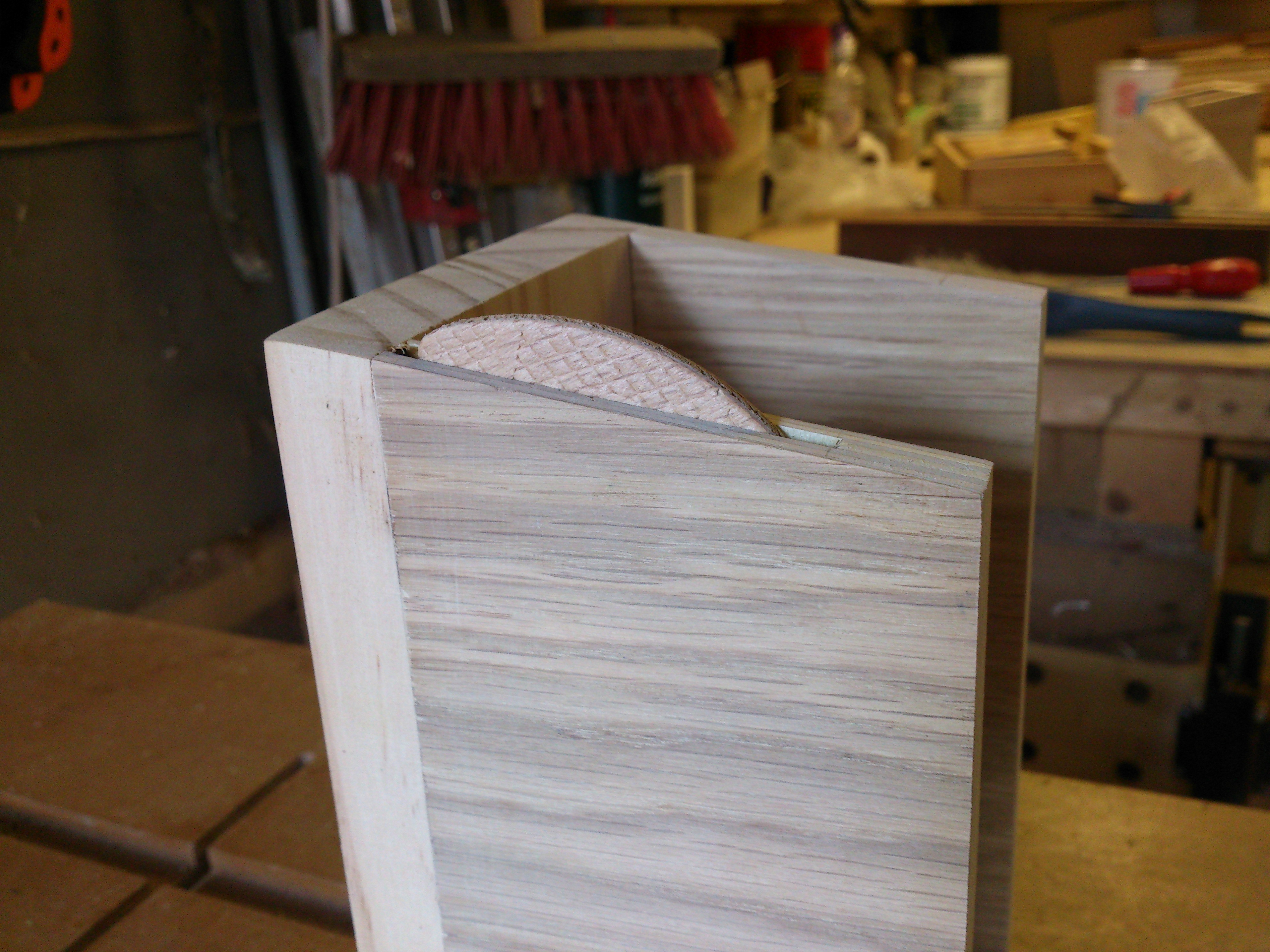
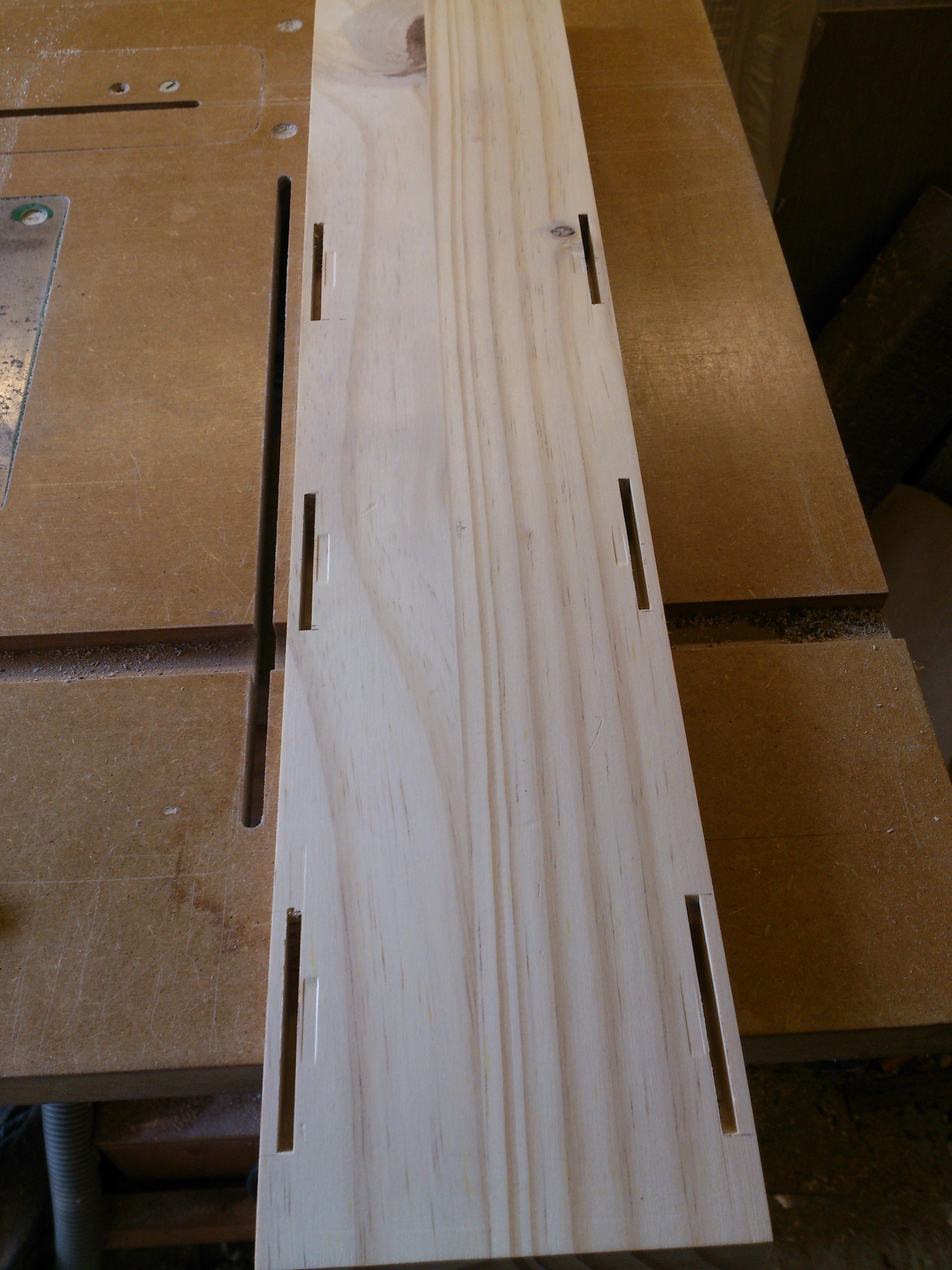
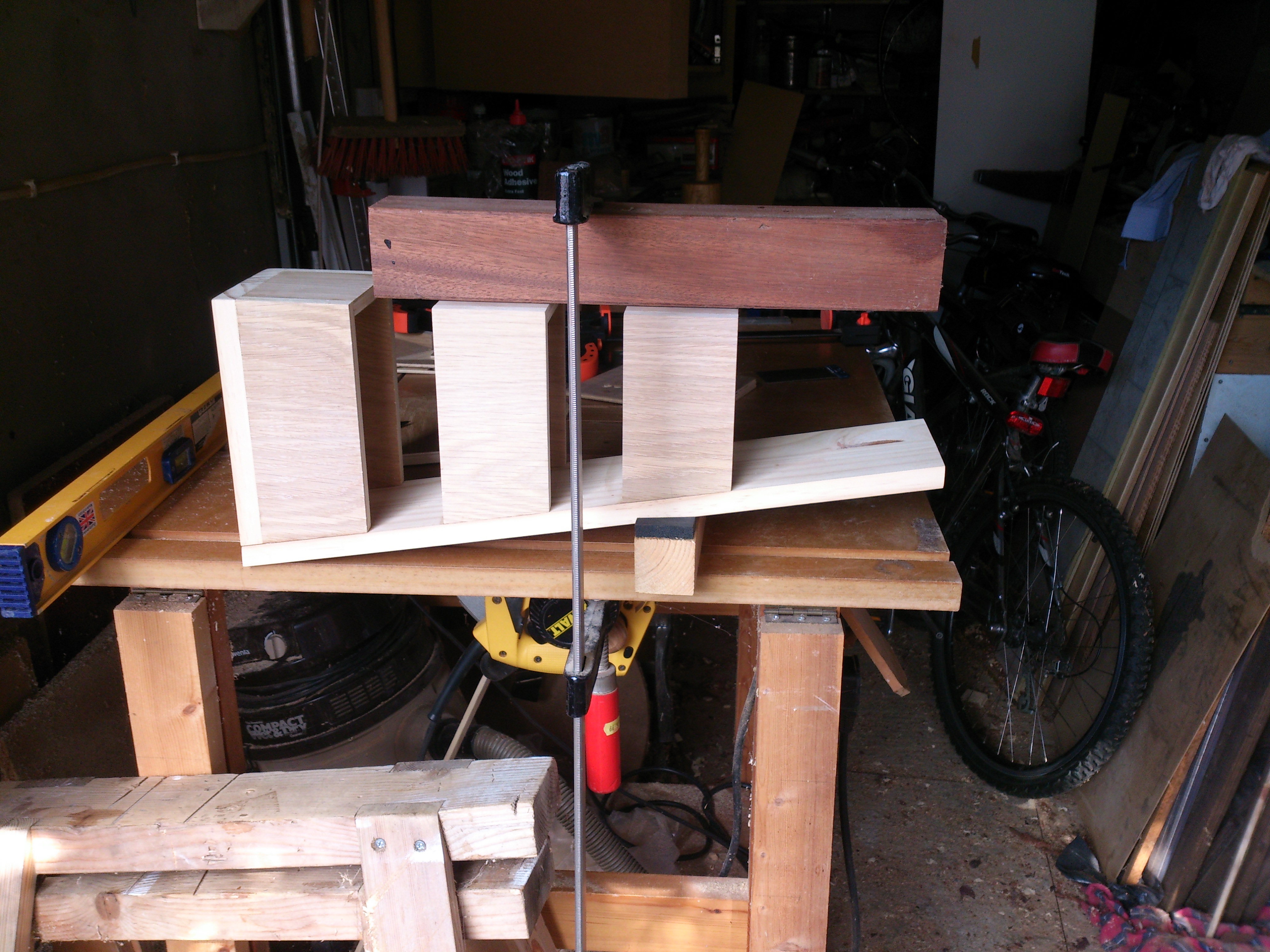
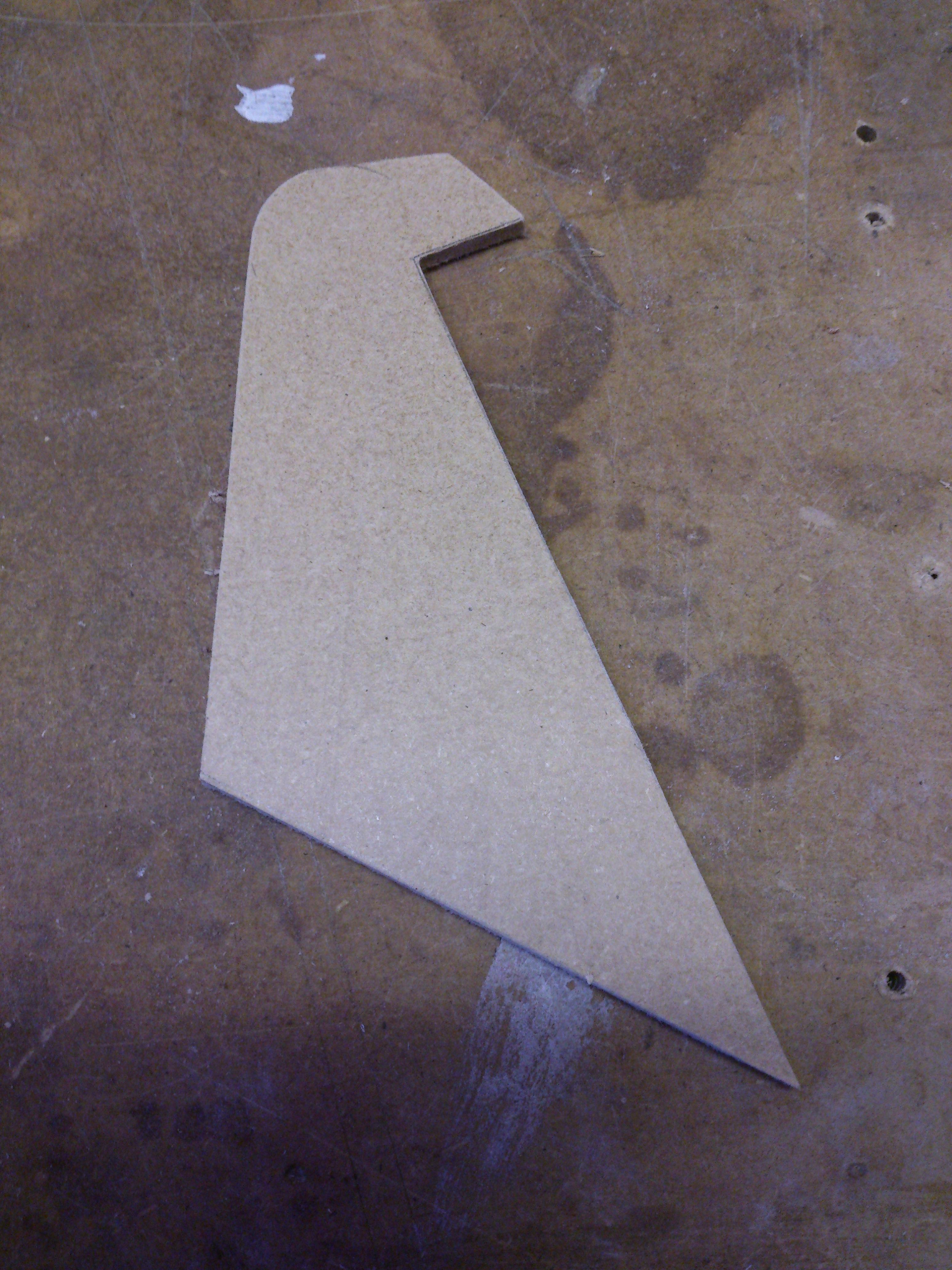
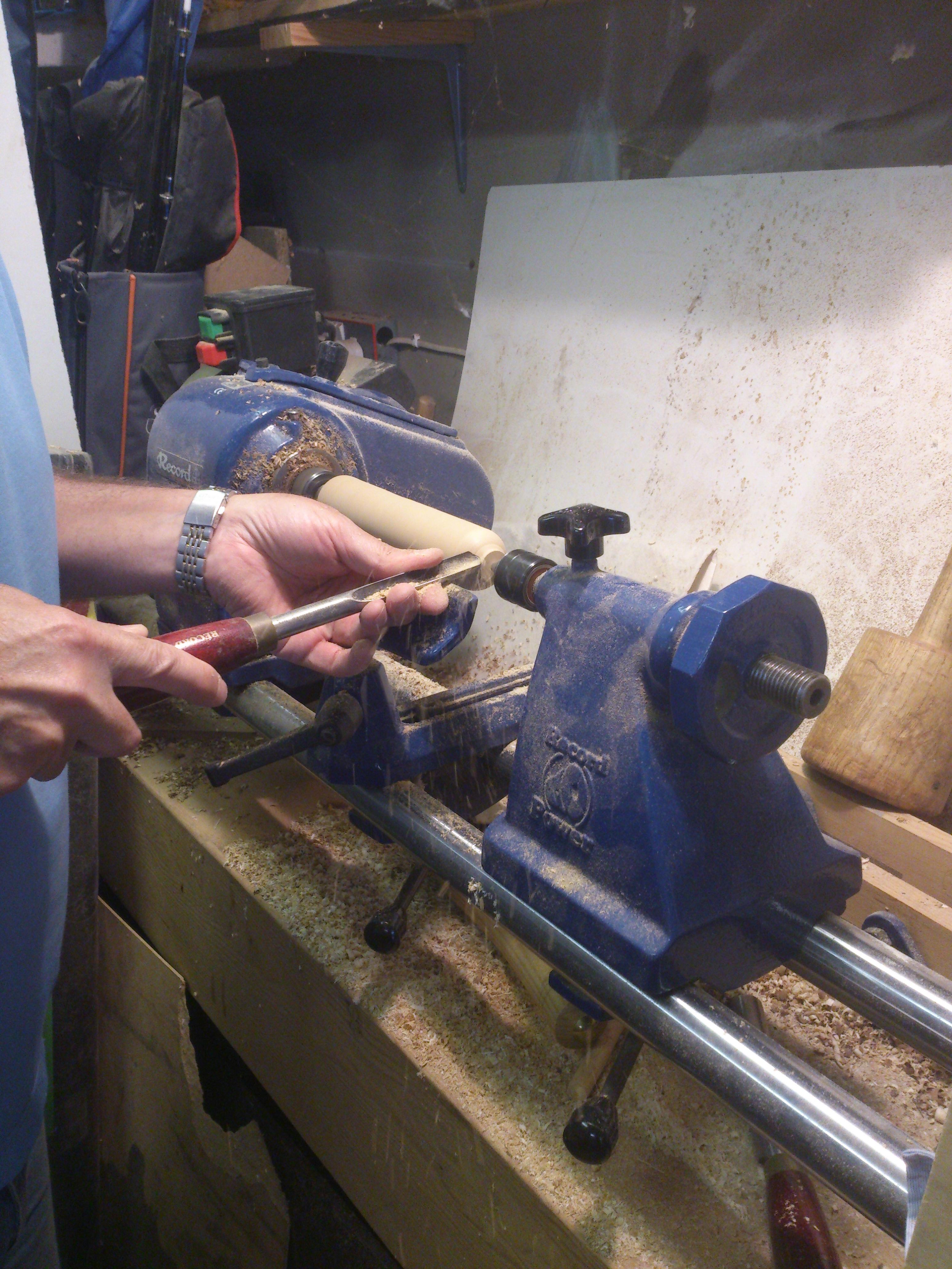
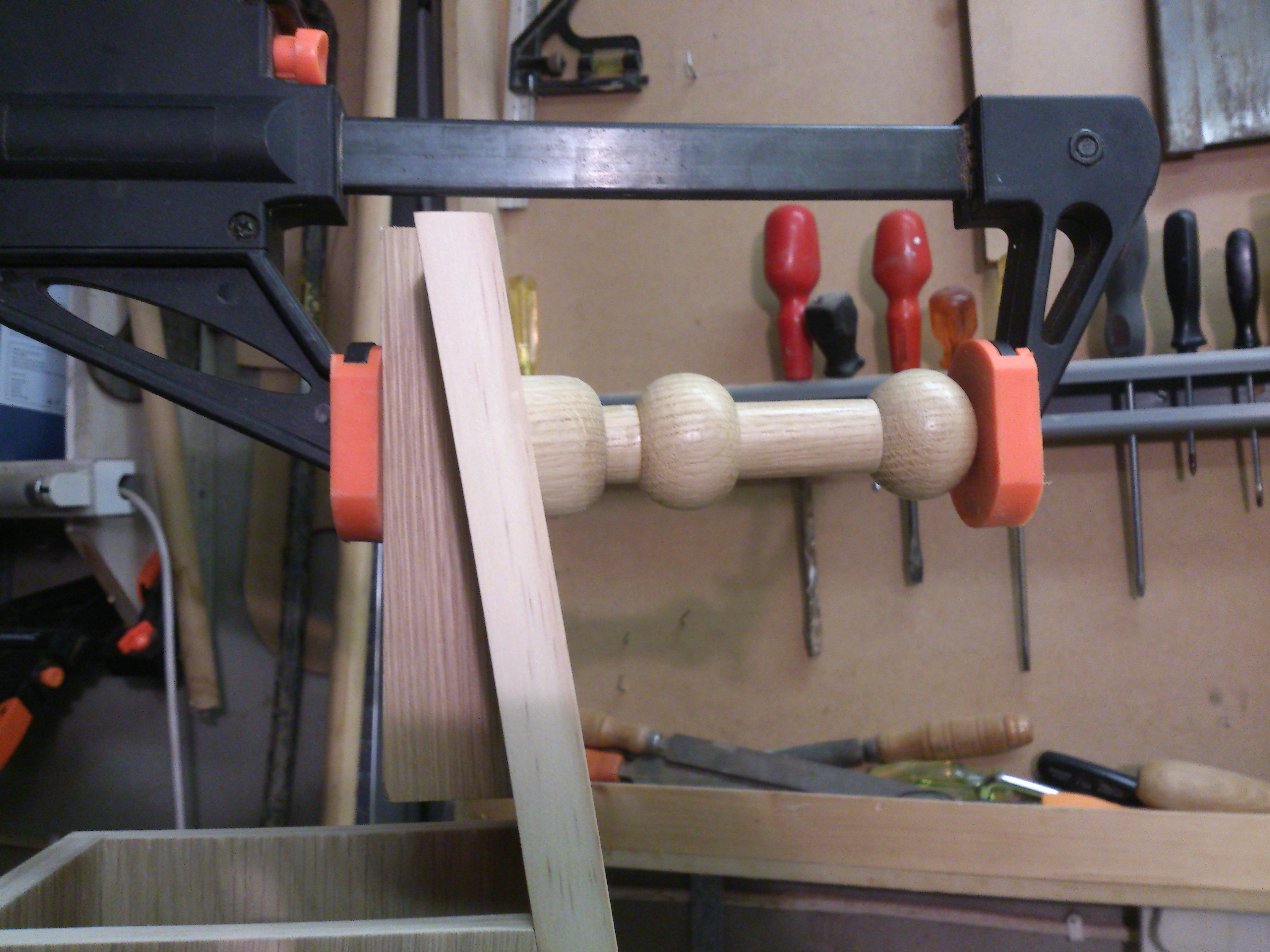
Headphone stands are pretty commonplace in home-offices, especially in the houses of audiophiles and gamers. There are countless horror stories of gamers running over their headphone wire and ruining their overpriced, bass-washed headphones; typically more LED than speaker cone... A very similar problem occurs with controller cables, especially those pesky xbox 360 controllers that are so commonplace (at the time of making). In order to escape the risk of damaging my headphones or controllers, I decided to design and make a simple wooden rack to house them, and their wires. After I decided the front of the rack should be slanted, the controllers should be held from the bottom and that I wanted to use a lathe, I drew the simple design, picture right, in CAD (well, sketch-up.. I couldn't get better free CAD software in 2015 without pirating.)
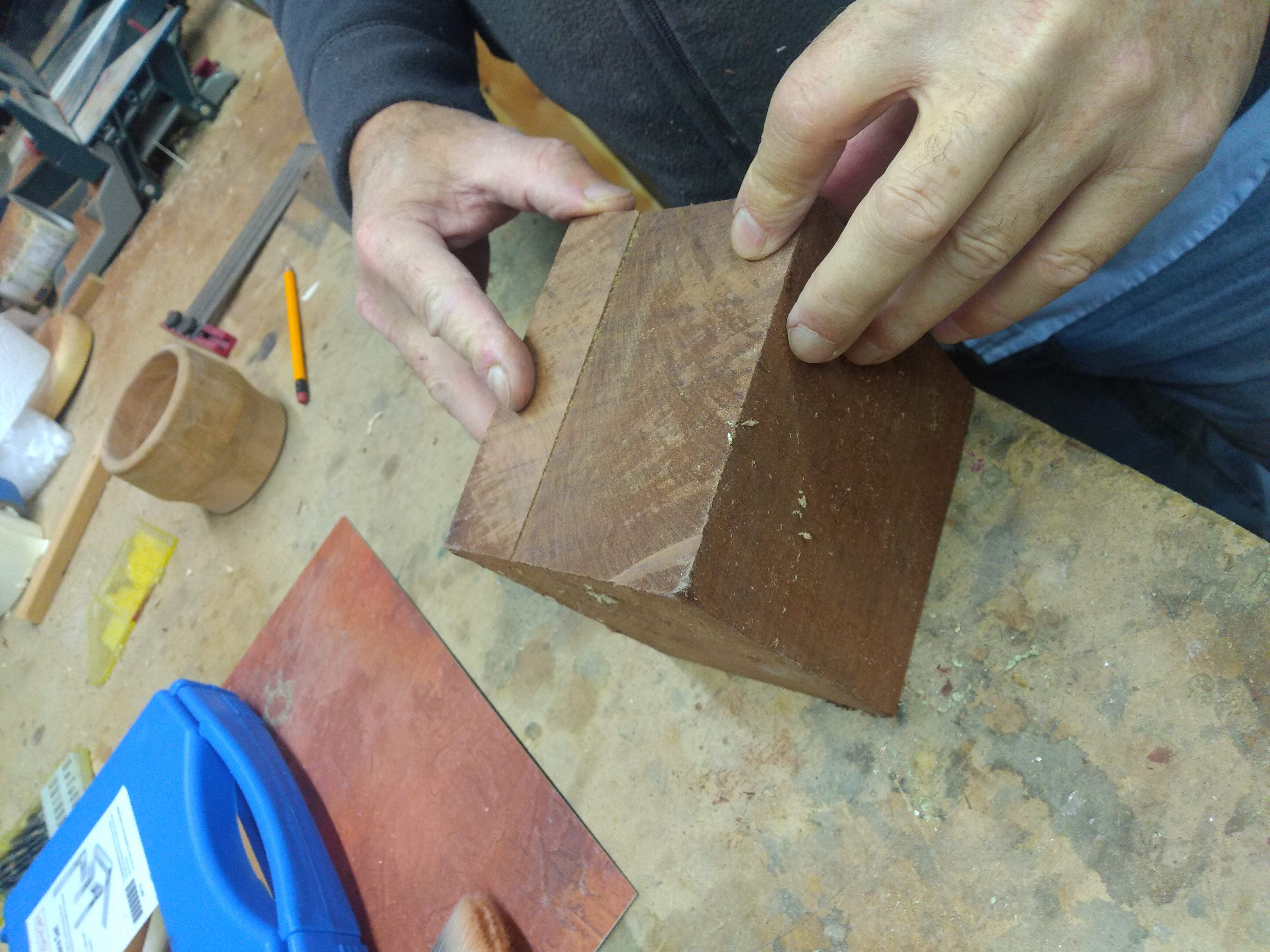
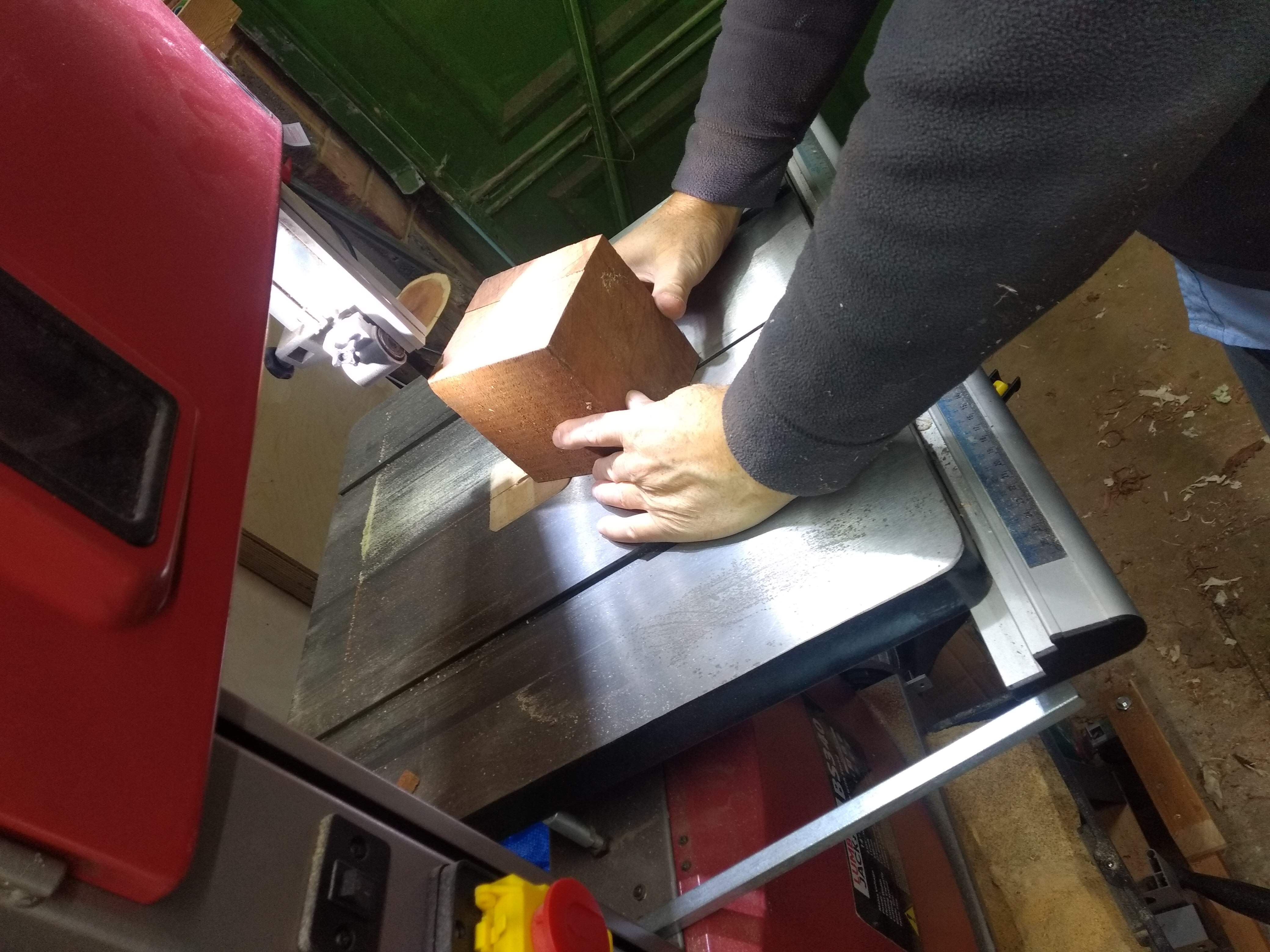
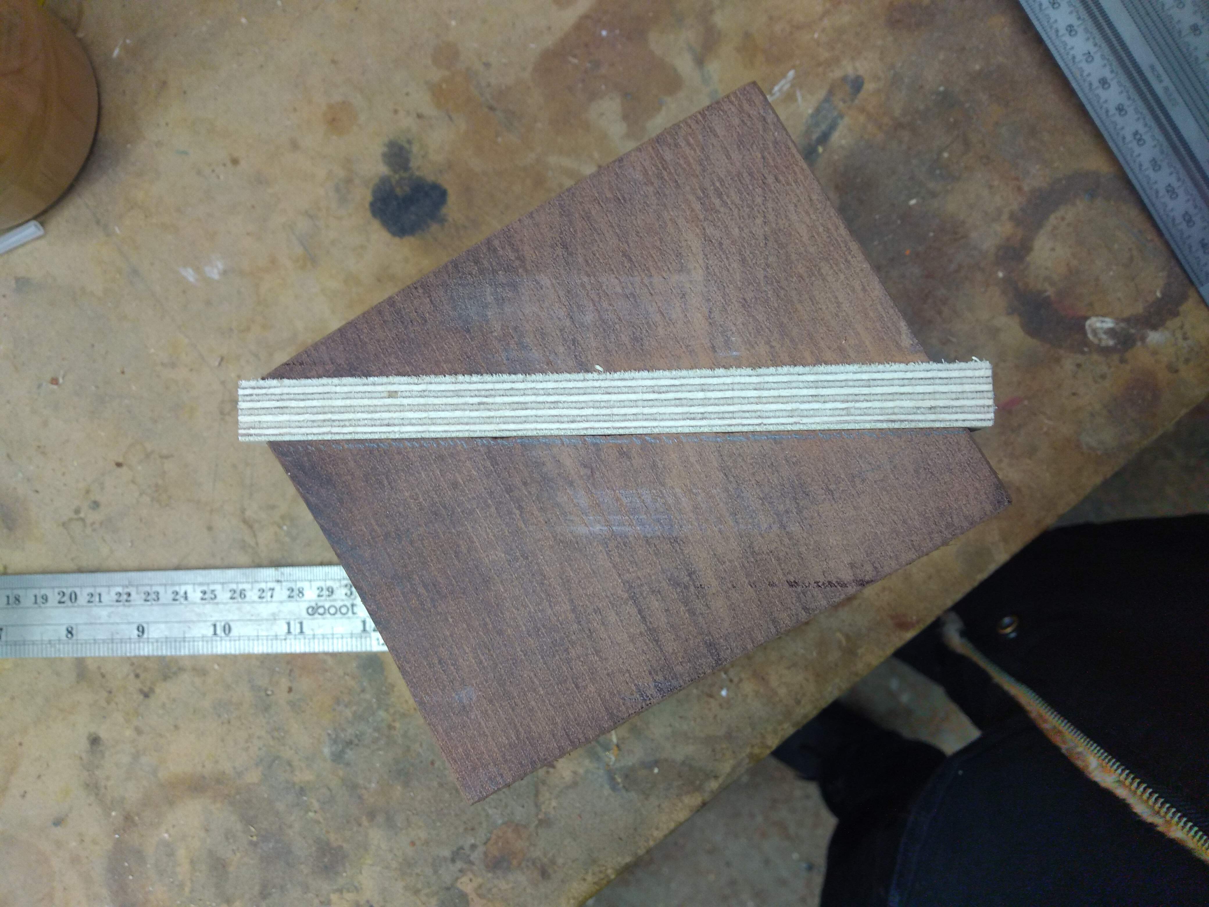
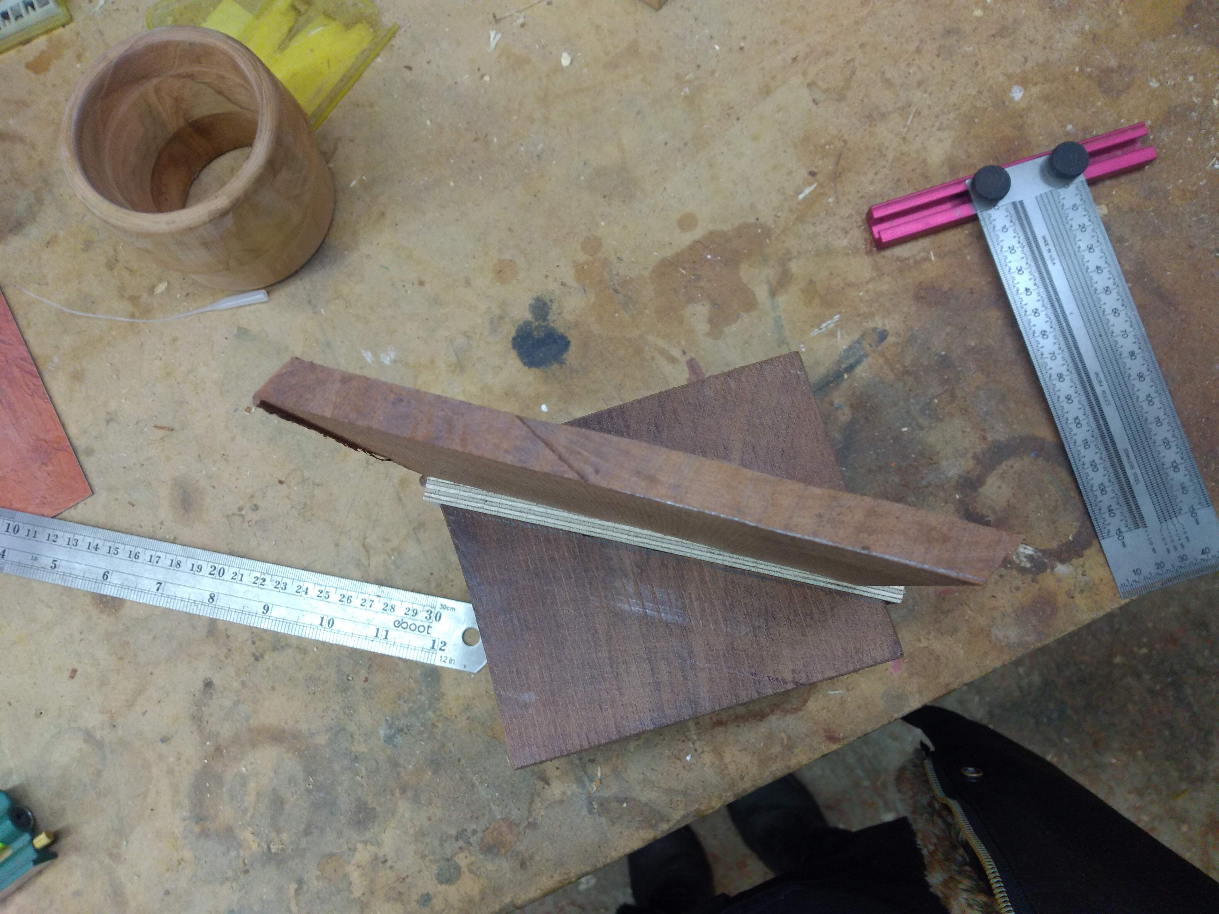
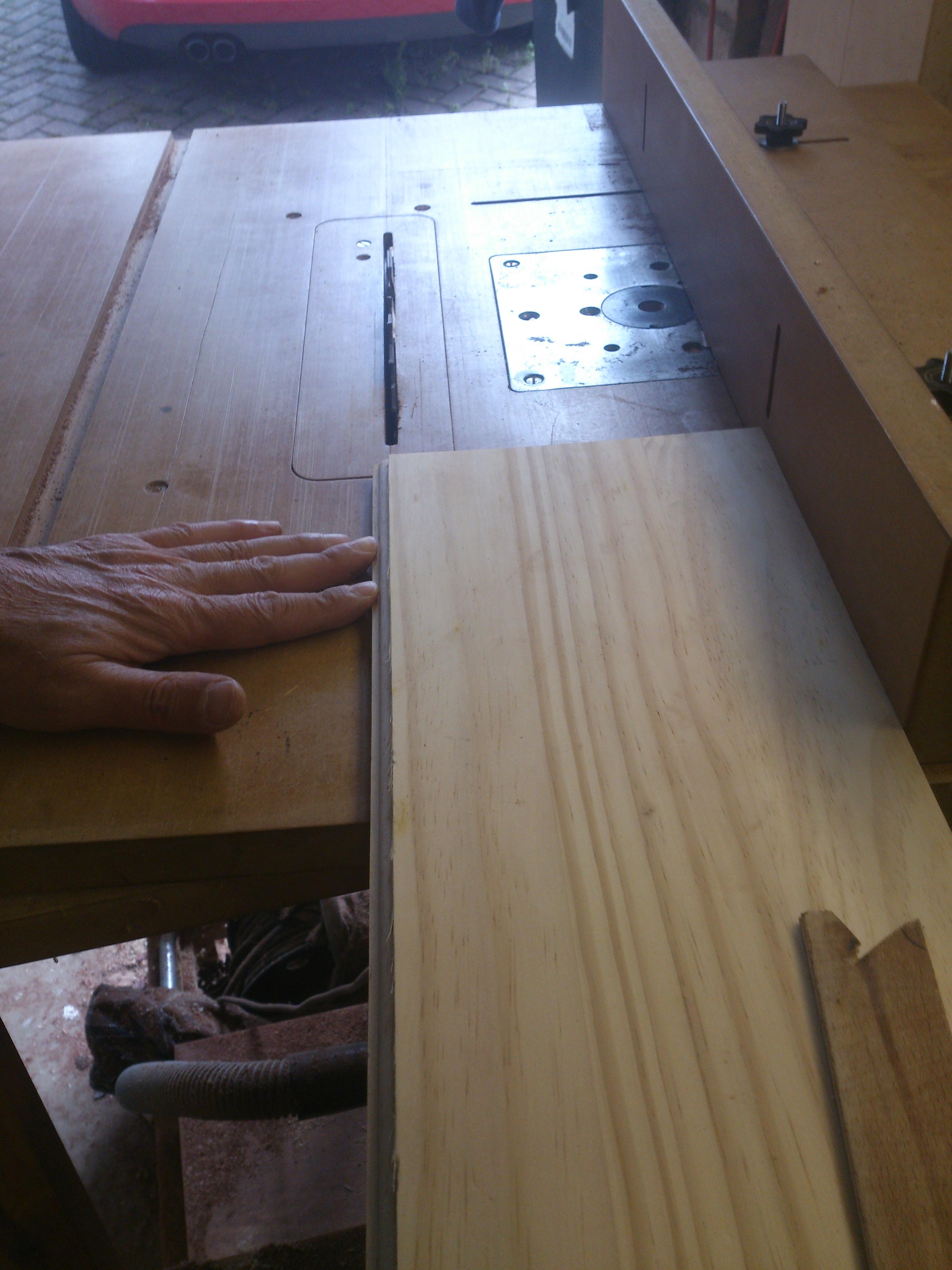
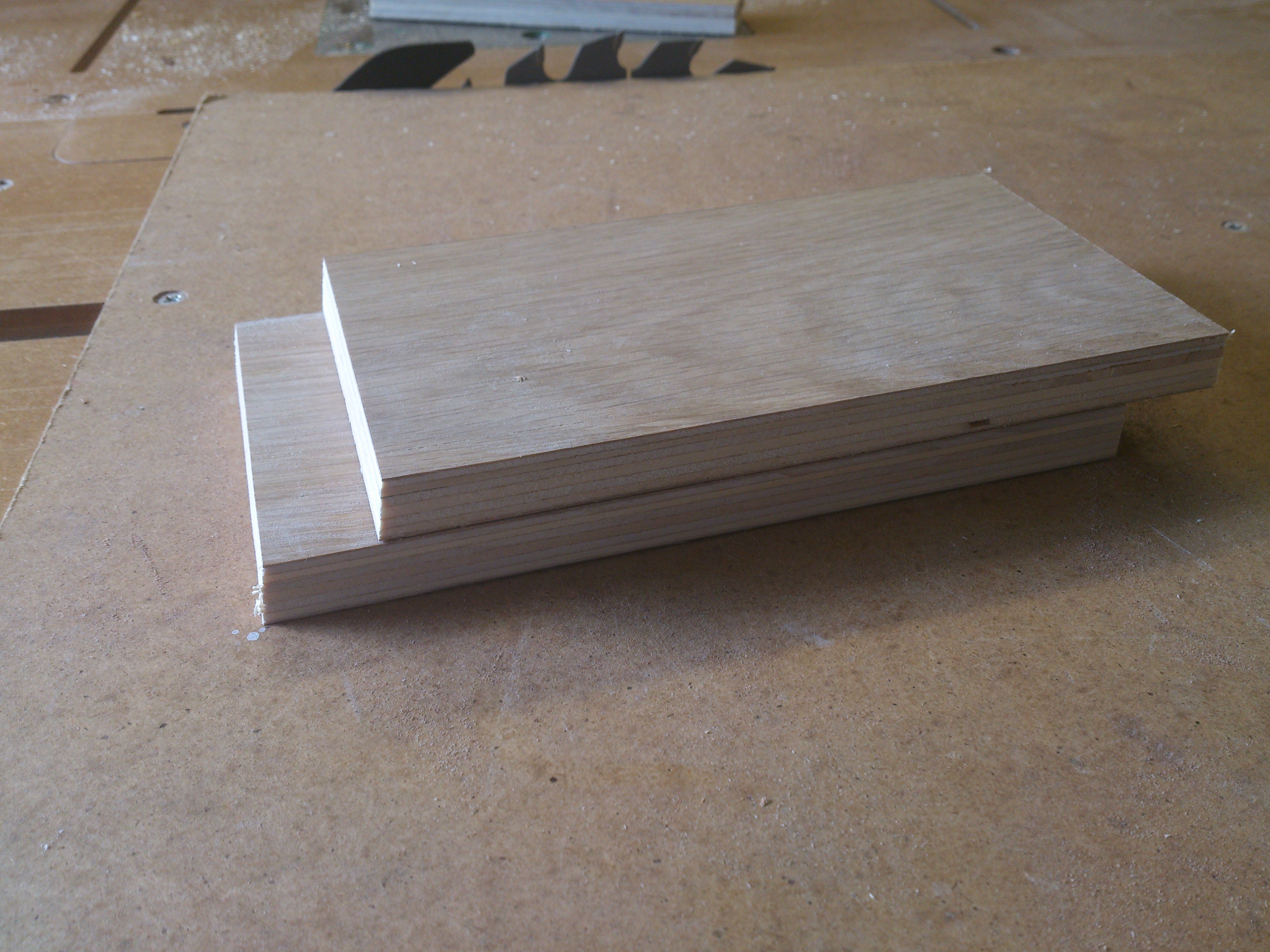
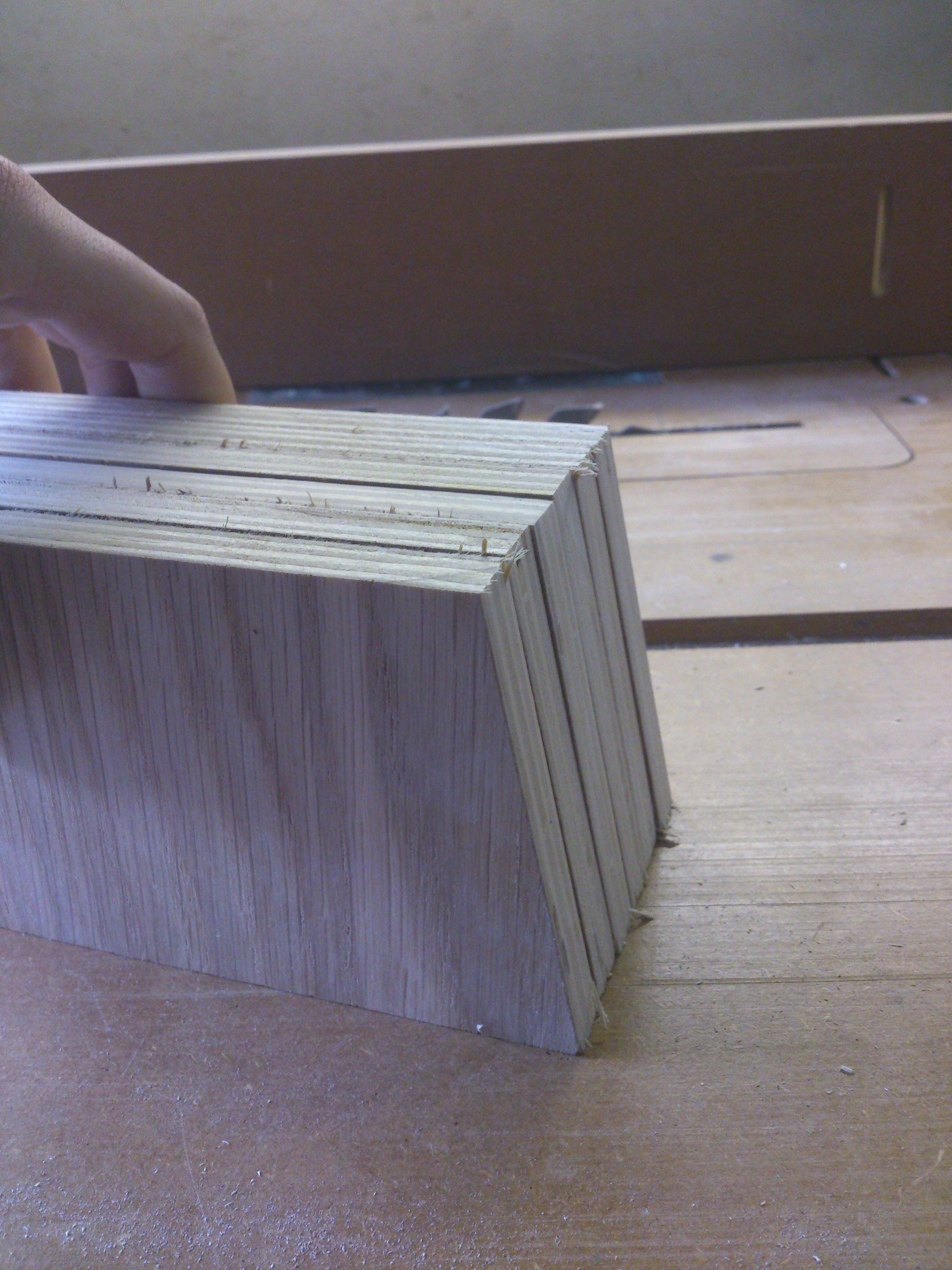
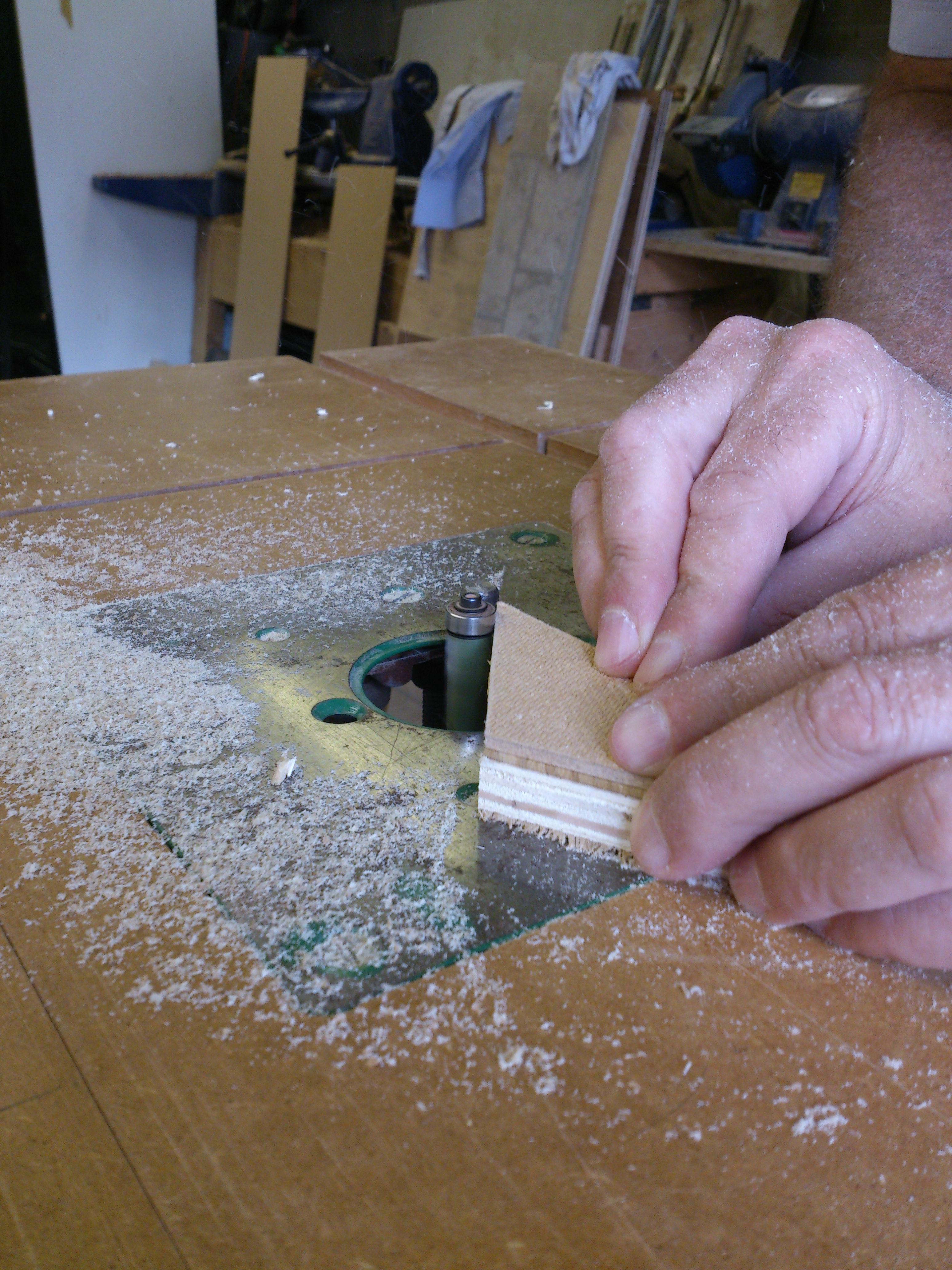
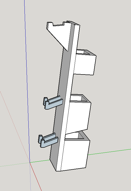 For this design, keeping the angle on the bevel and making back-up references was the only way to ensure that the cable caddies could be parallel to the bottom and flush with the front panels. Solid pine was chosen for the front and bottom pieces and the caddies were made from 7-layer marine ply left-over from the bed project.
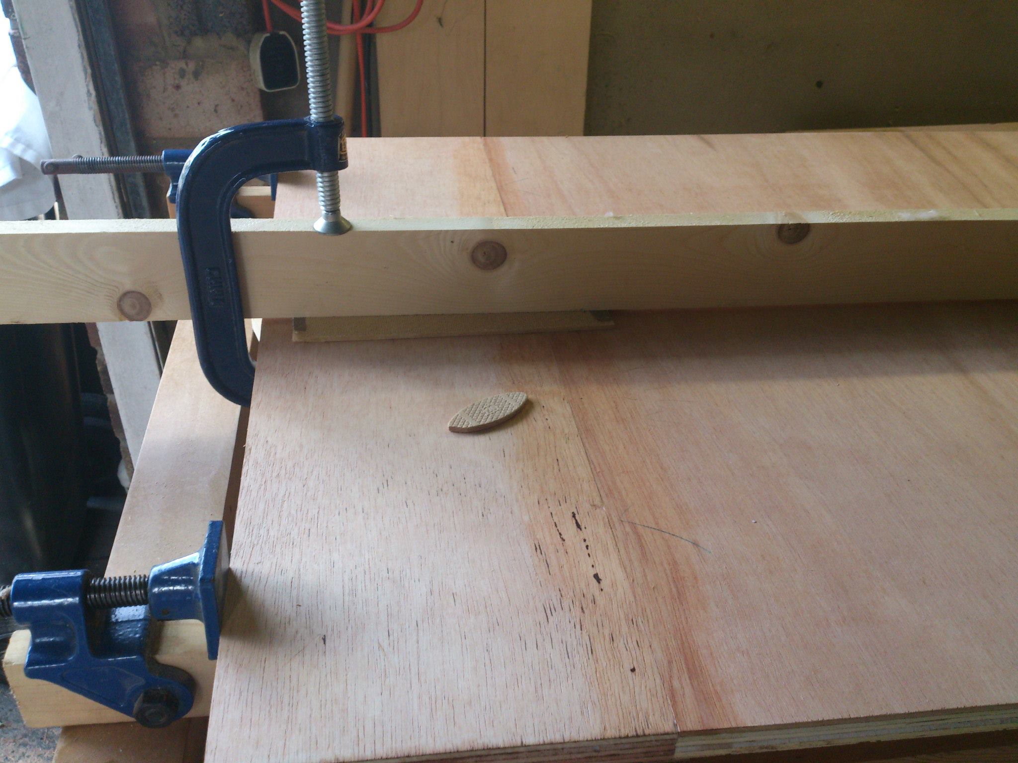
The most challenging part of the build was definitely the clamping. Turns out ~12° is not an easy angle to hold things at.
Once it was glued up, it was coated in a few coats of linseed oil, sanding in between coats. The final product, pictured right, has seen continuous use since it's build and has survived many moves during study. Overall, a fantastic product.
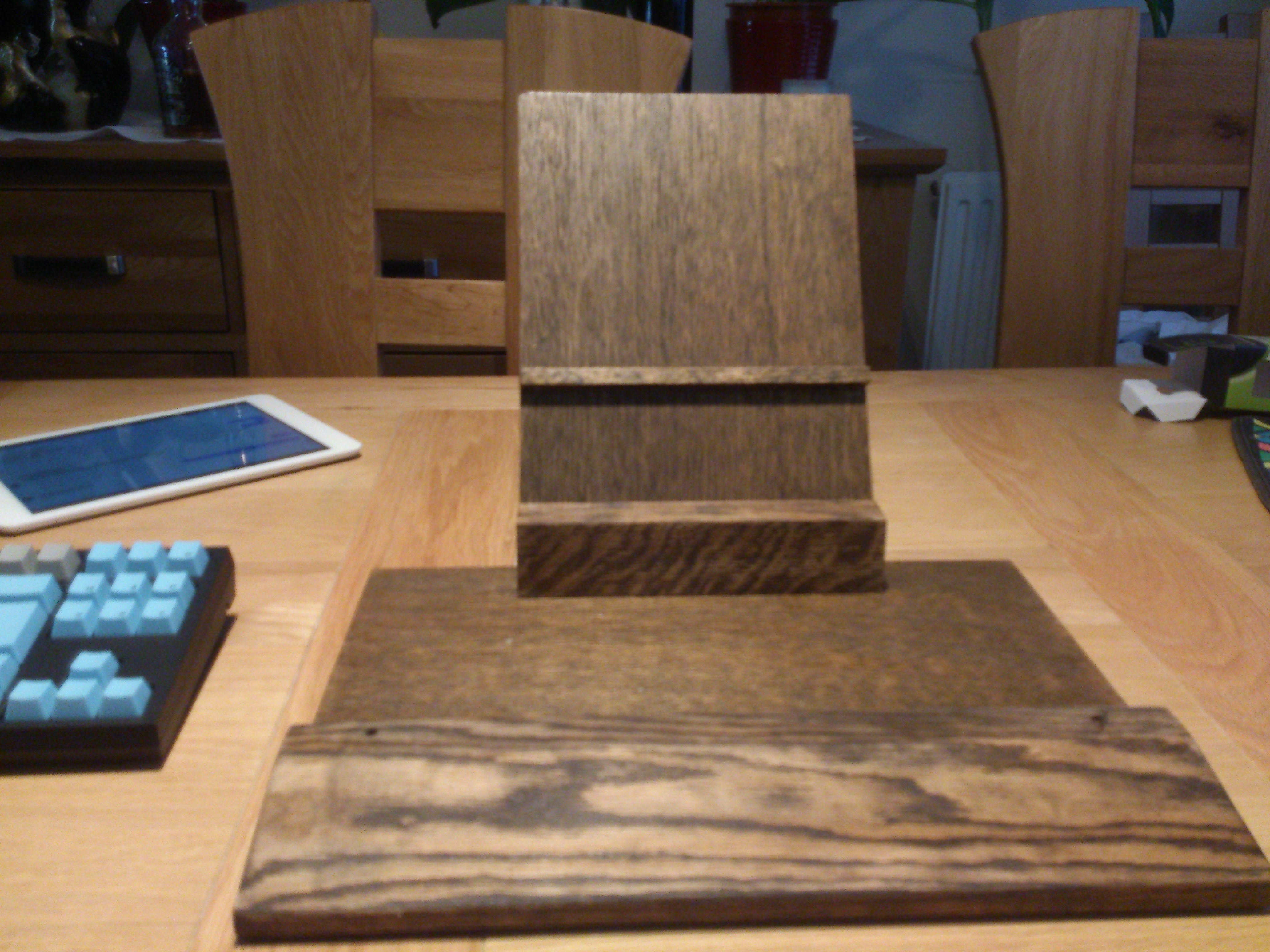
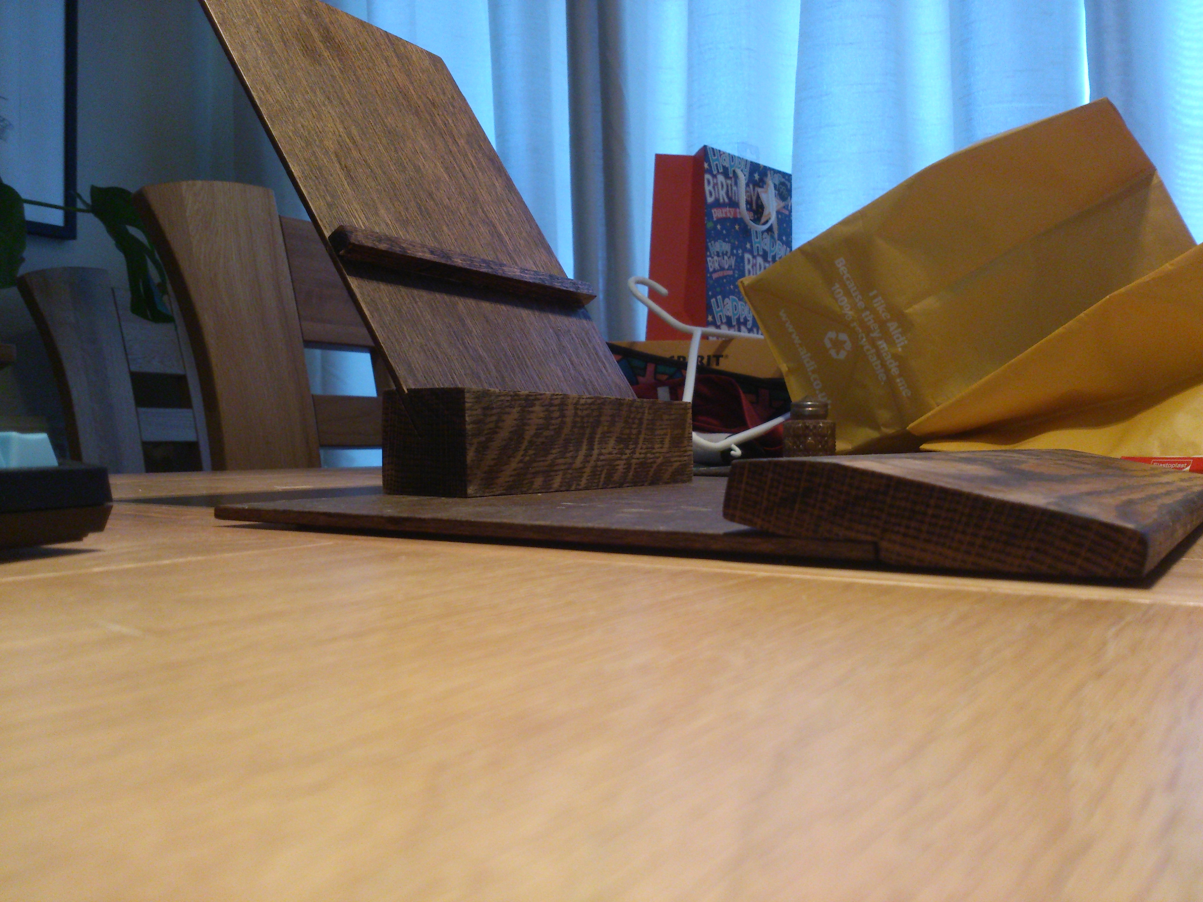
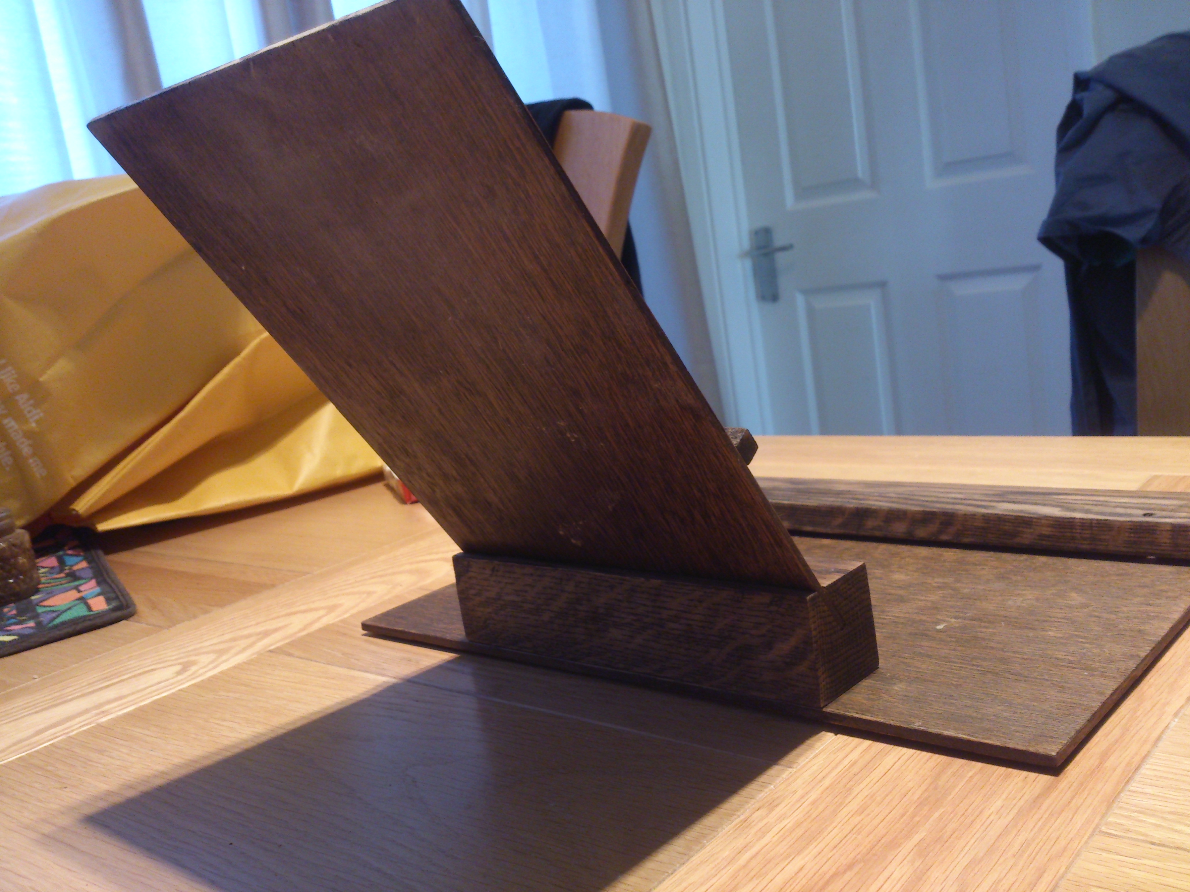
Kablet Stand
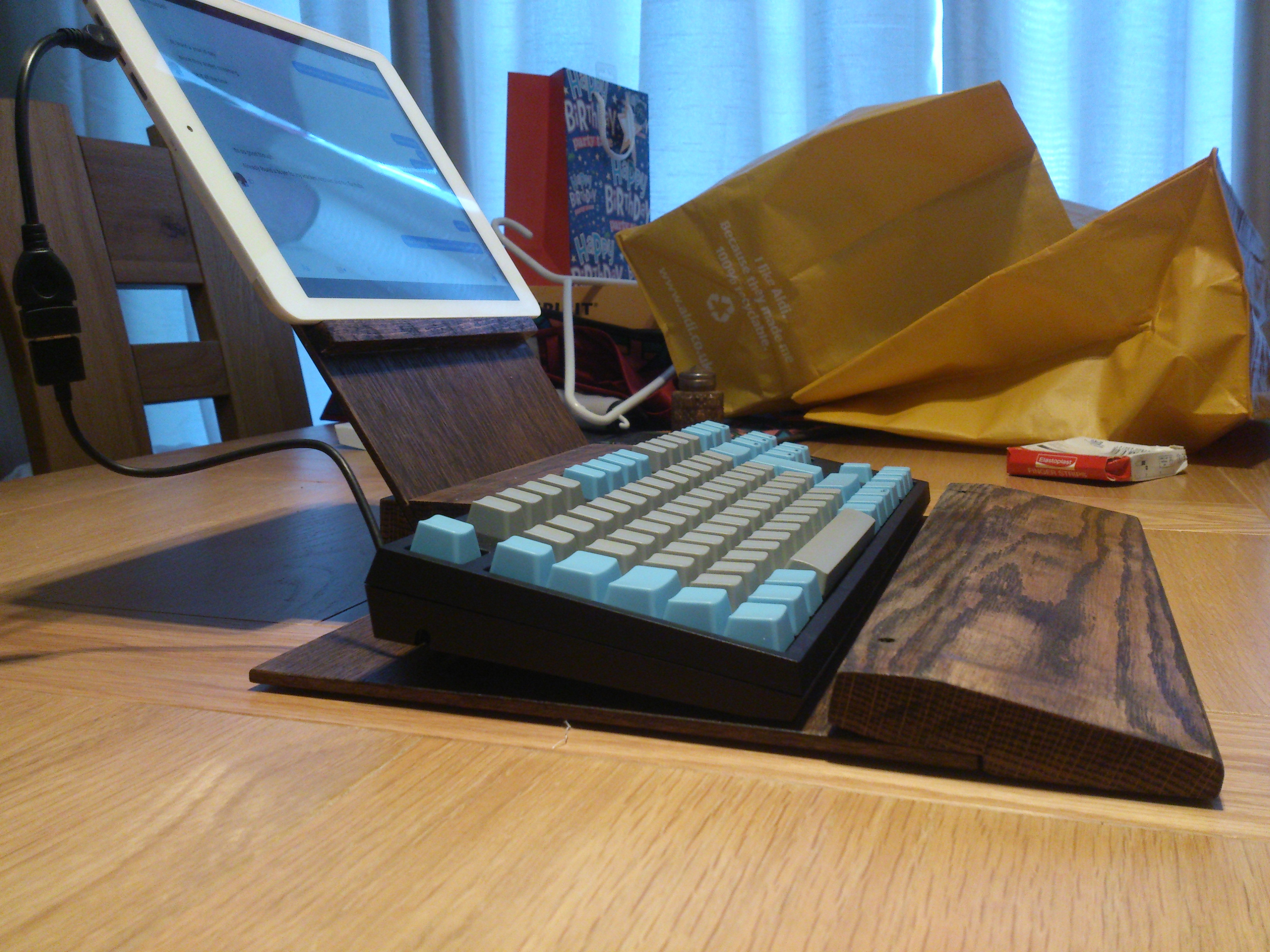
At the time of making this, I had just lost my laptop and was waiting on the Lenovo T420 I knew I was getting for christmas. In the interim, I needed a way to SSH into the server my brother and I were sharing (primarily to host game servers on to play together). A phone wouldn't do since the screen was too small and the phone I had at the time was so pathetic. I have a knock-off Chinese tablet that I still occasionally use and it supported USB-OTG (On The Go)! This meant that, with the appropriate adapter, a keyboard and mouse could be used to control the device. With this in mind, and after struggling to find an ergonomic way to use the tablet with a keyboard, I set about making a tablet stand that doubled as a wrist wrest for the WASD keyboard I had (and still have). The "kablet stand" as I called it is pictured right, where I was not using a mouse anymore since a touchscreen was more than sufficient.
Futon Bed Project
Things that I use everyday are the things I like to make into the best possible experience. This is why I need settings on computers, I need to change the colour schemes on text editors and PDF readers, I need to use a mechanical keyboard, I need to use a fountain pen, I need a customised and responsive phone (note responsive, not powerful or overly fancy). These needs stem from the discomfort bad options bring, especially when using them for extended periods, as is common for typing reports etc. This same urge later led to the headphone stand and wrist rest projects above.
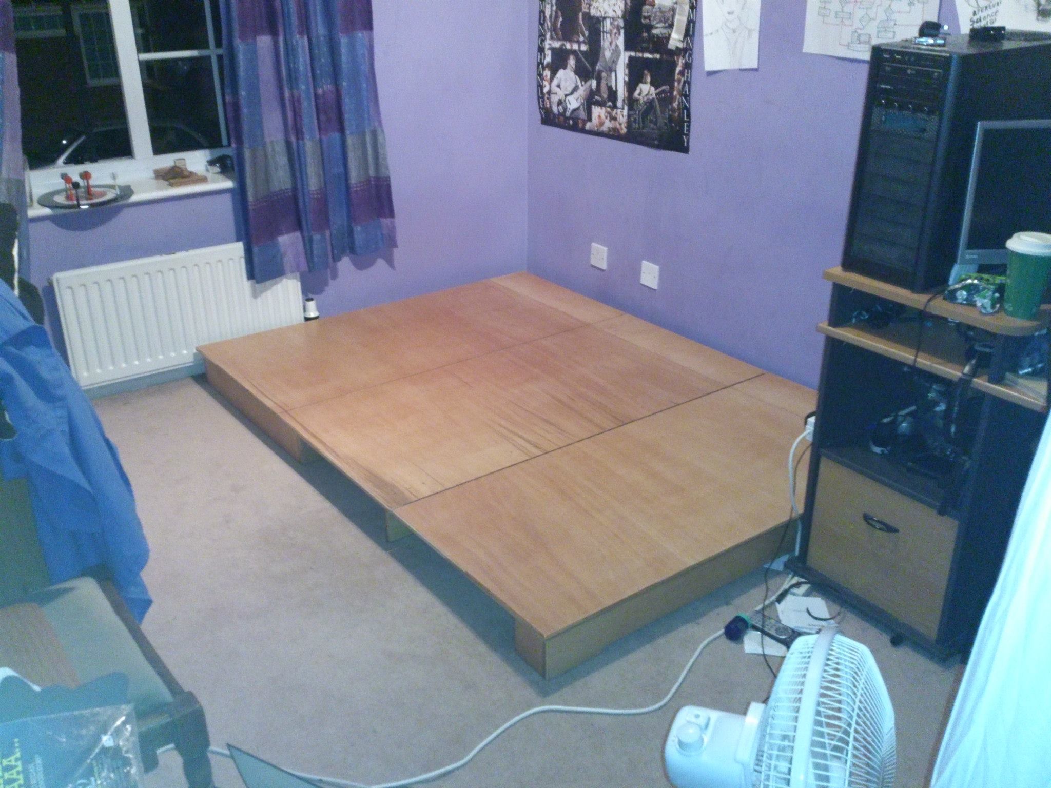
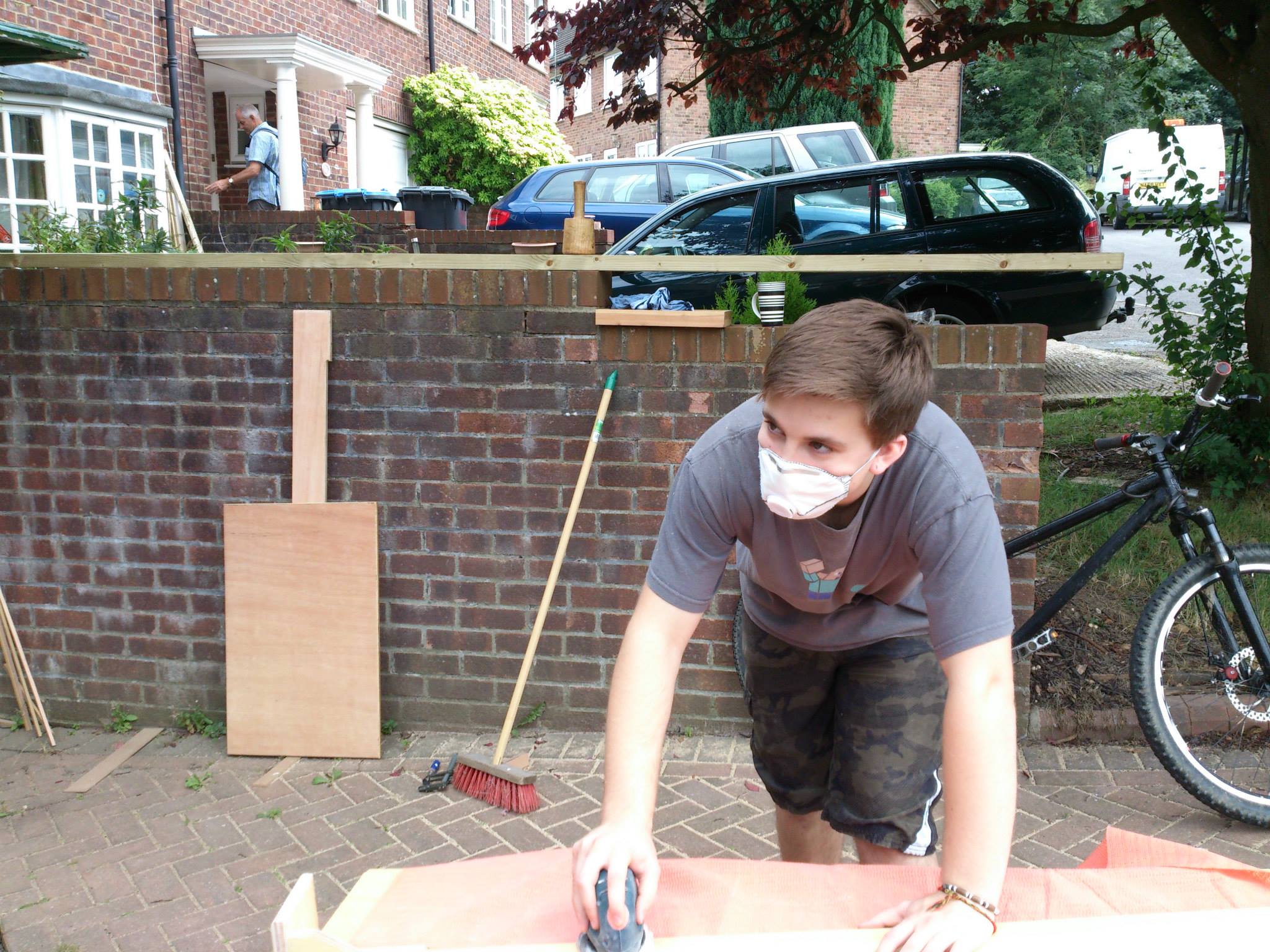
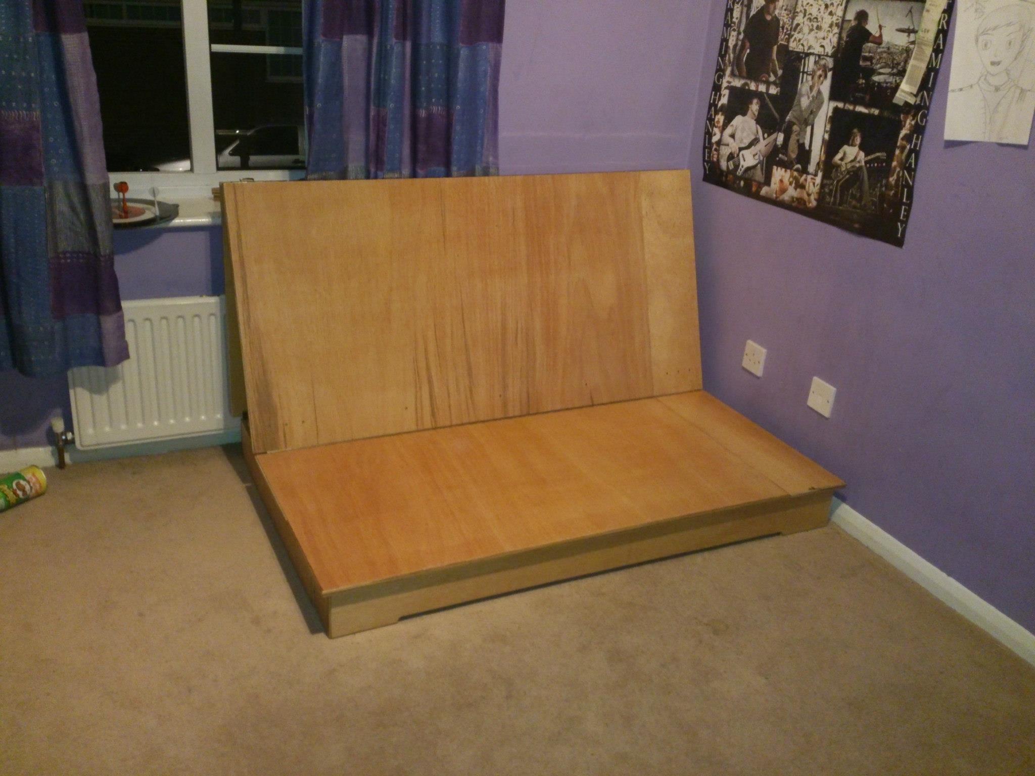
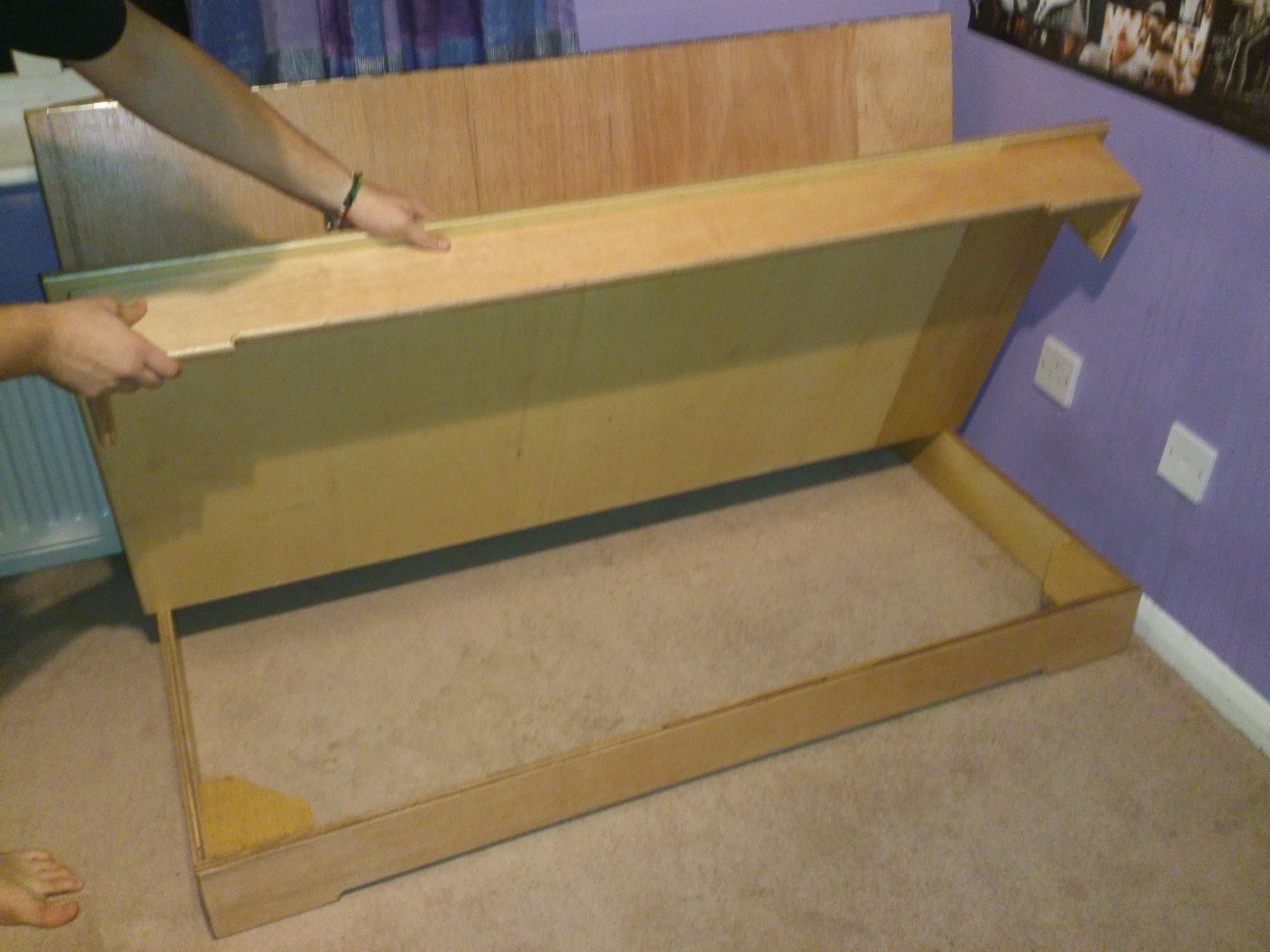
For this, the bed I originally had was the bottom half of a bunk bed bought for me when I was much younger. The top half had long broken and the bottom half survived long enough for it to serve as the only bed I remember having before making this one. It broke, and for a long while I had been sleeping with the mattress on the floor, waiting to decide what bed to buy and that sort of thing. Finding no options I liked, I decided to take it upon myself to make a queen sized futon that did not have the typical slats which cause the bed to feel lumpy and the night's sleep to be restless.
 Instead, I wanted to make a solid based bed. In the design process, it became apparent that I needed some more storage, primarily to store the boxes the computer parts and other consumer electronics came in. Finally I wanted the bed be a functional sofa for when I had visitors and we wanted to watch a film or play a game.
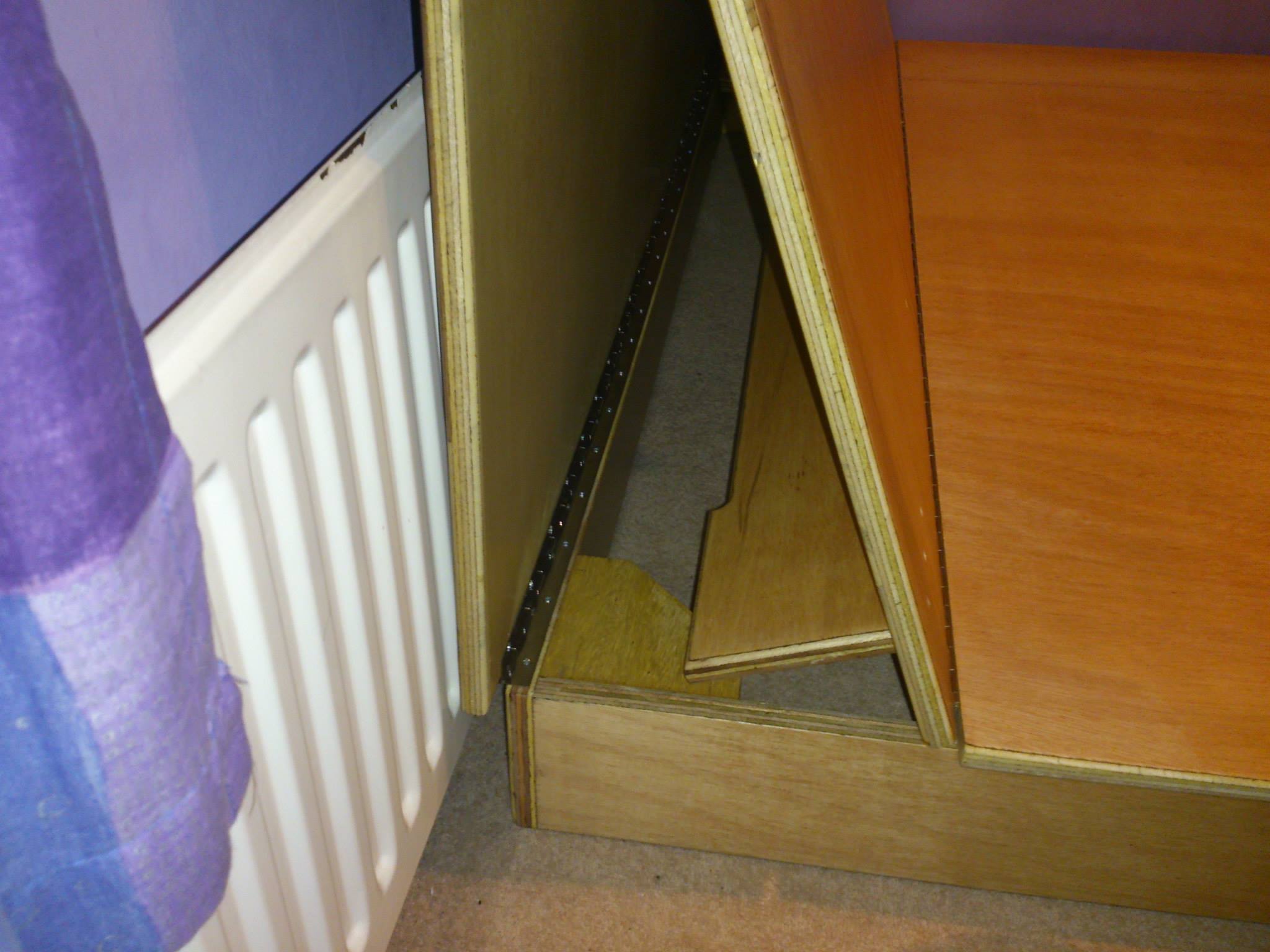
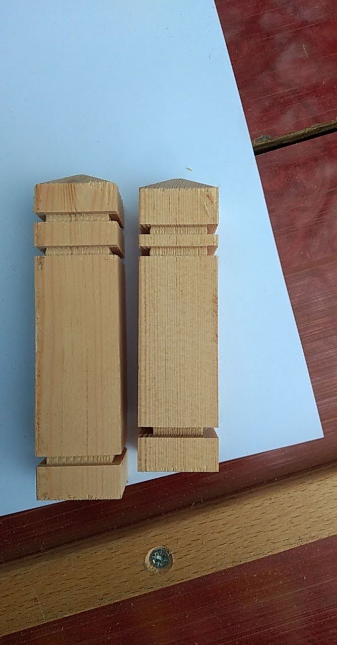
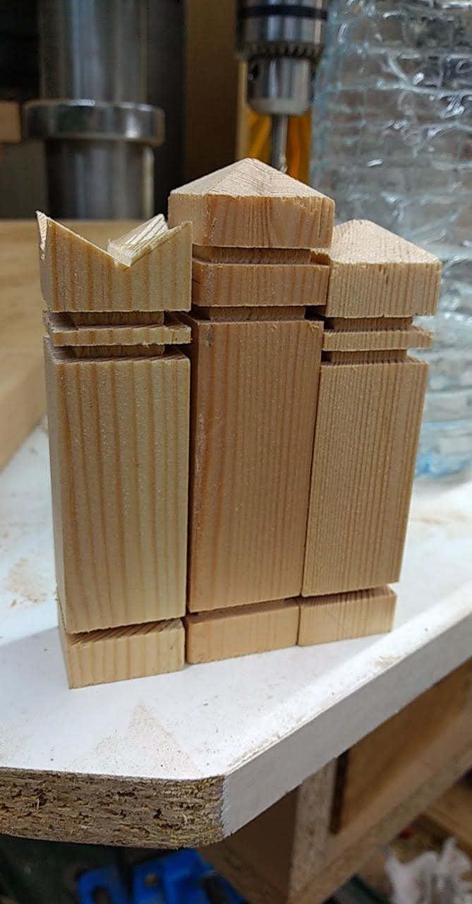
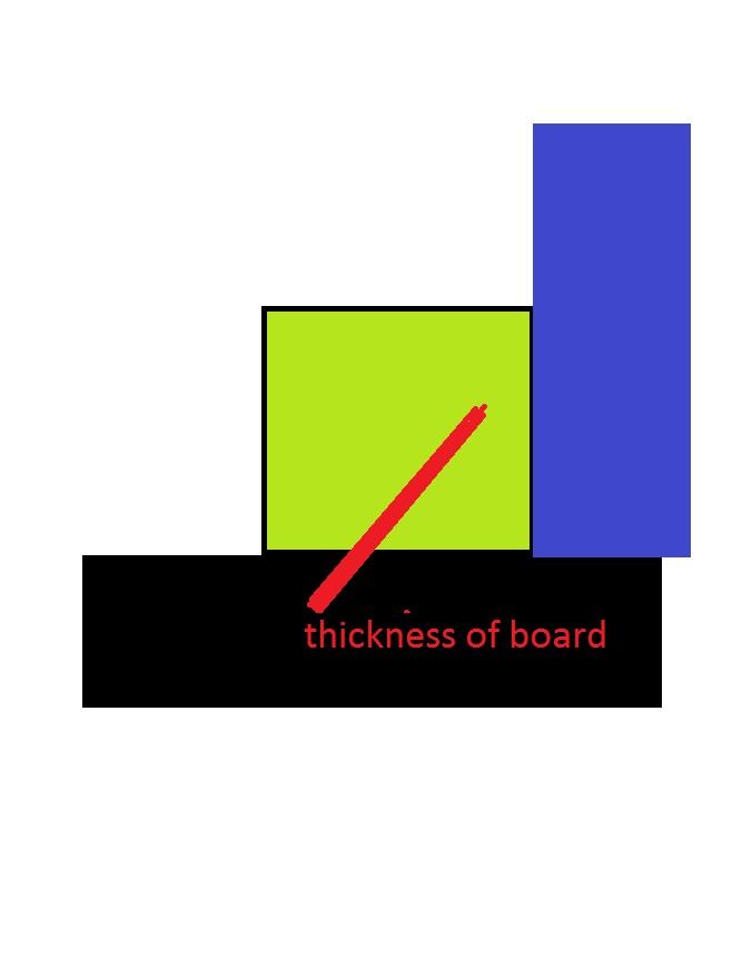
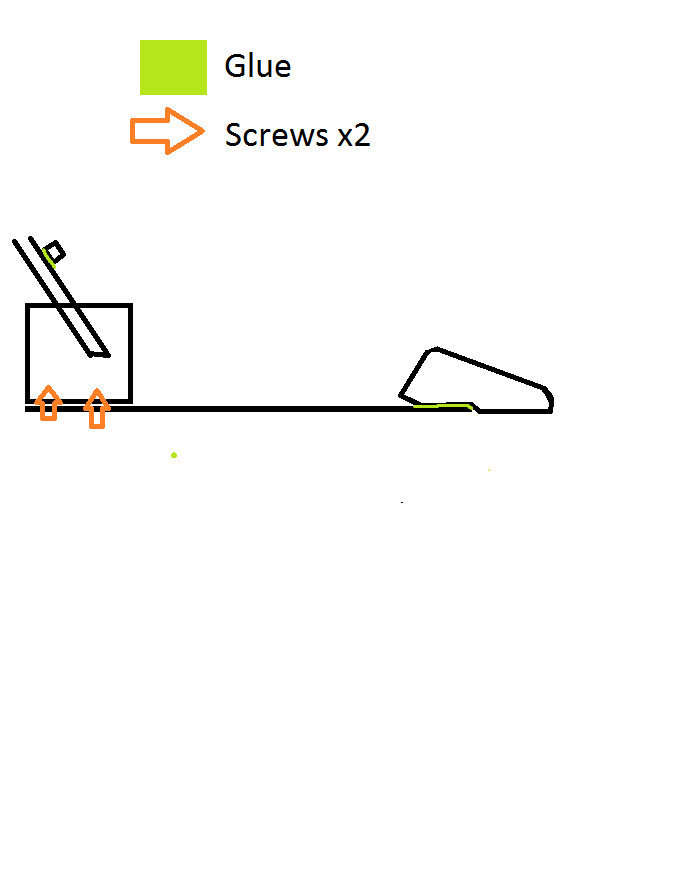
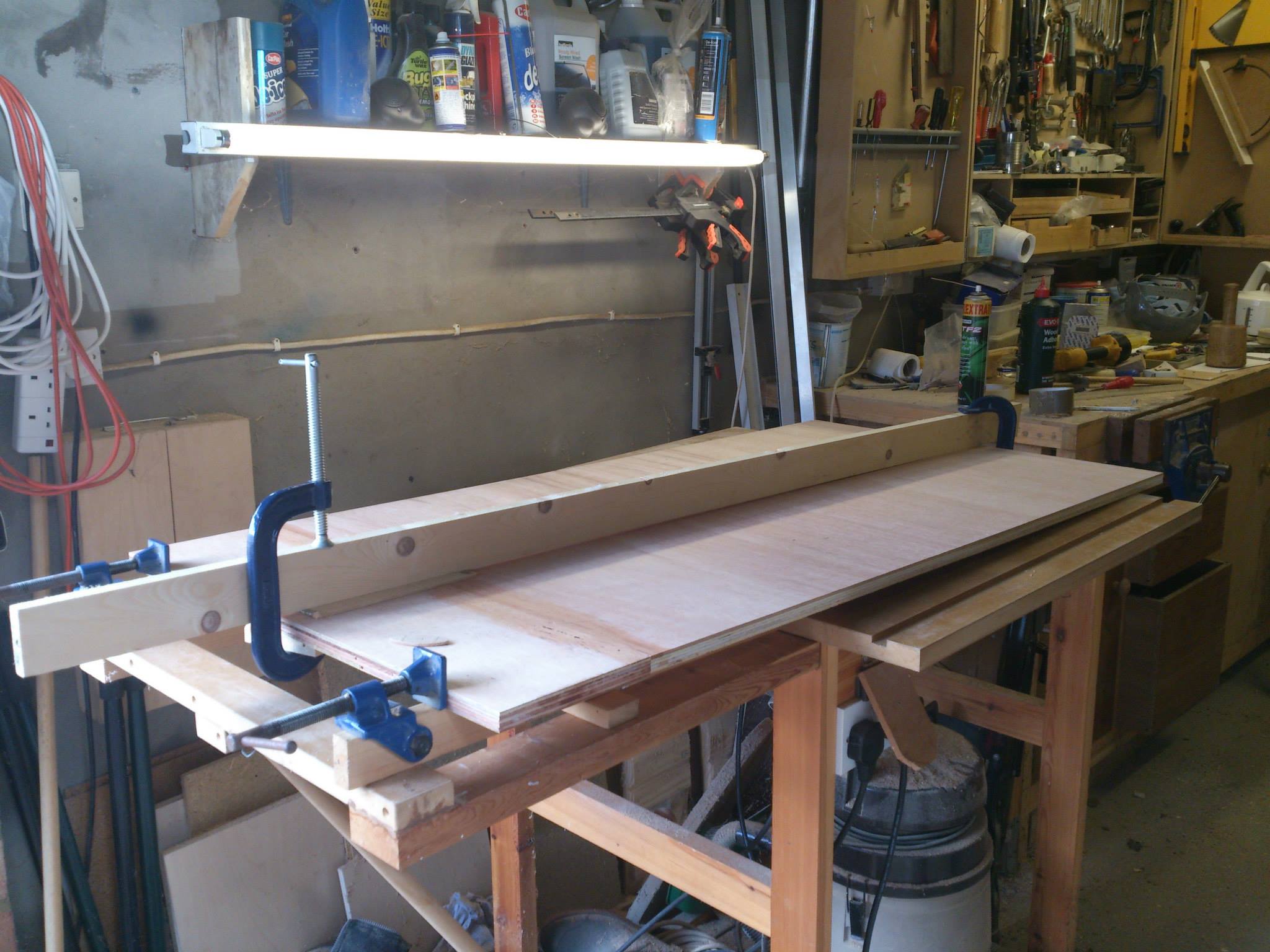
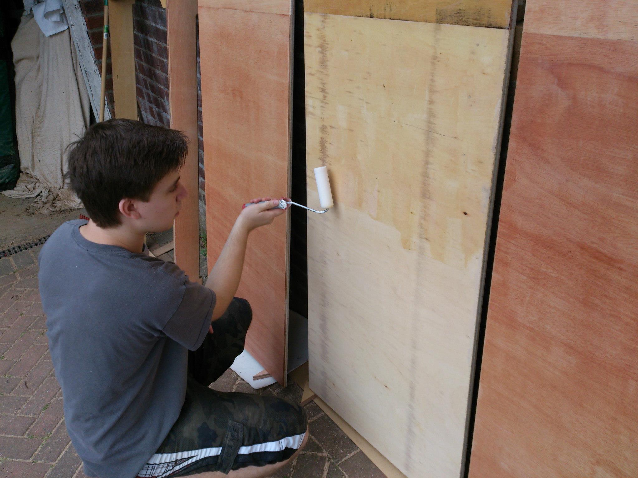
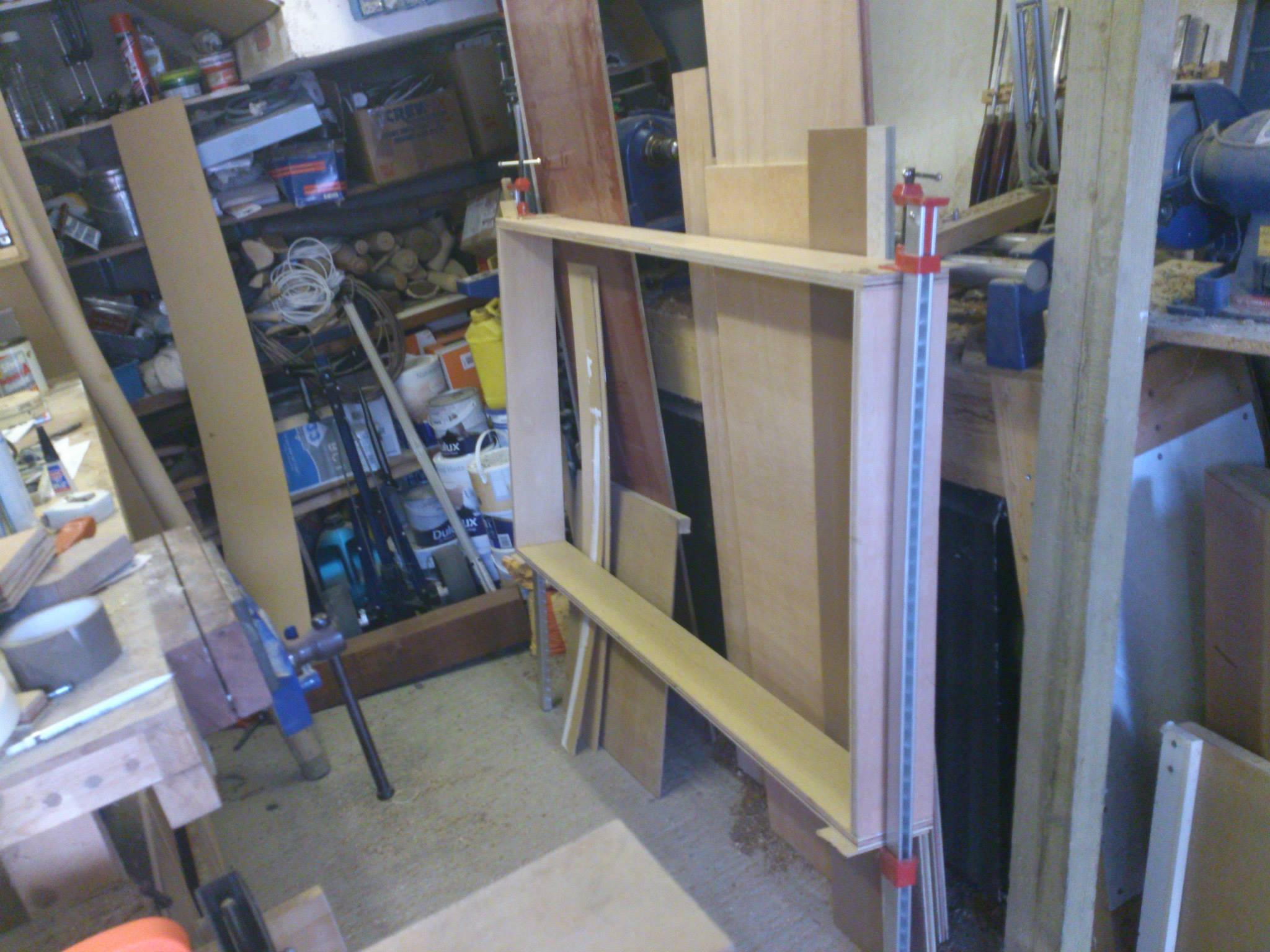
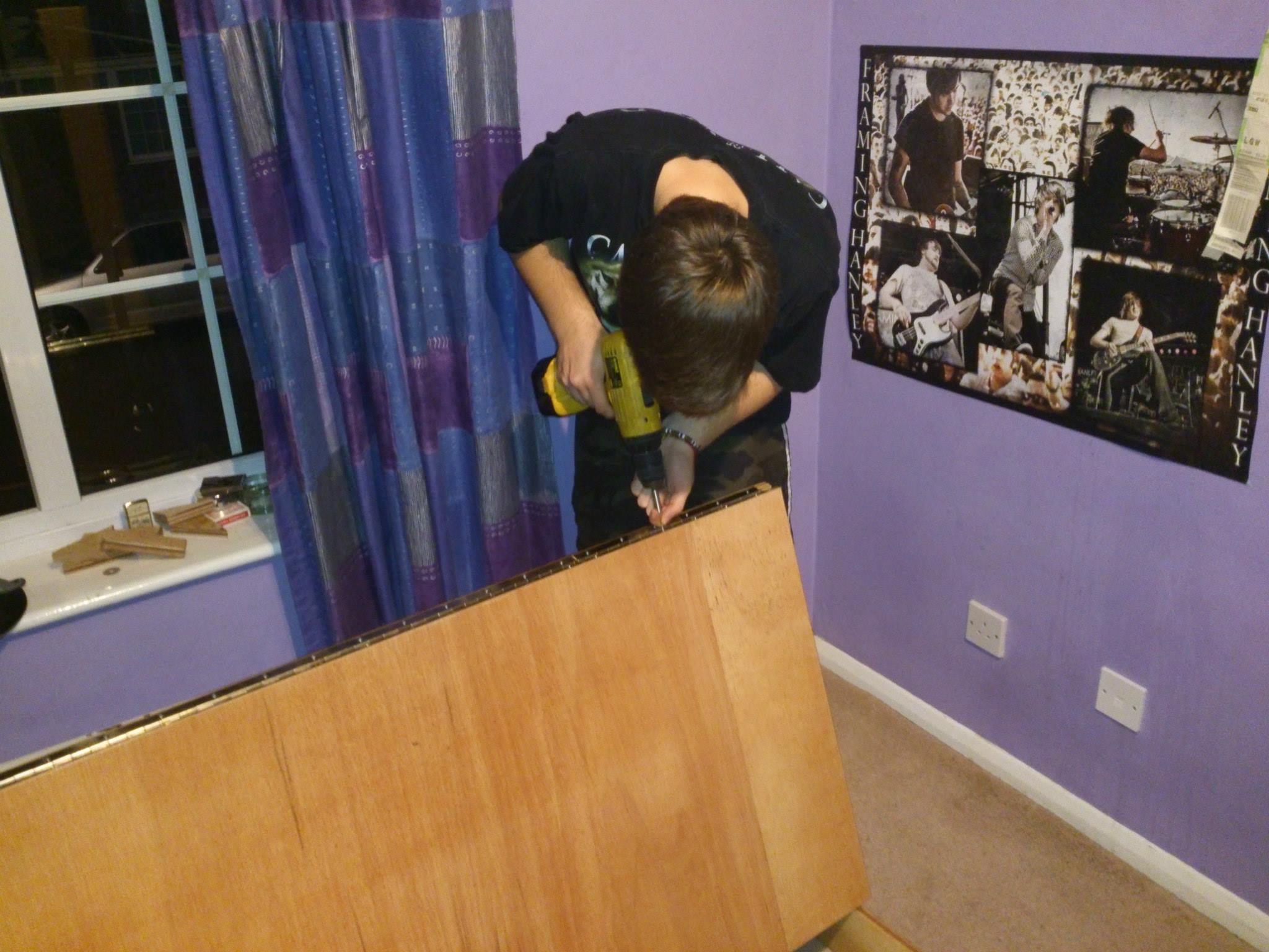
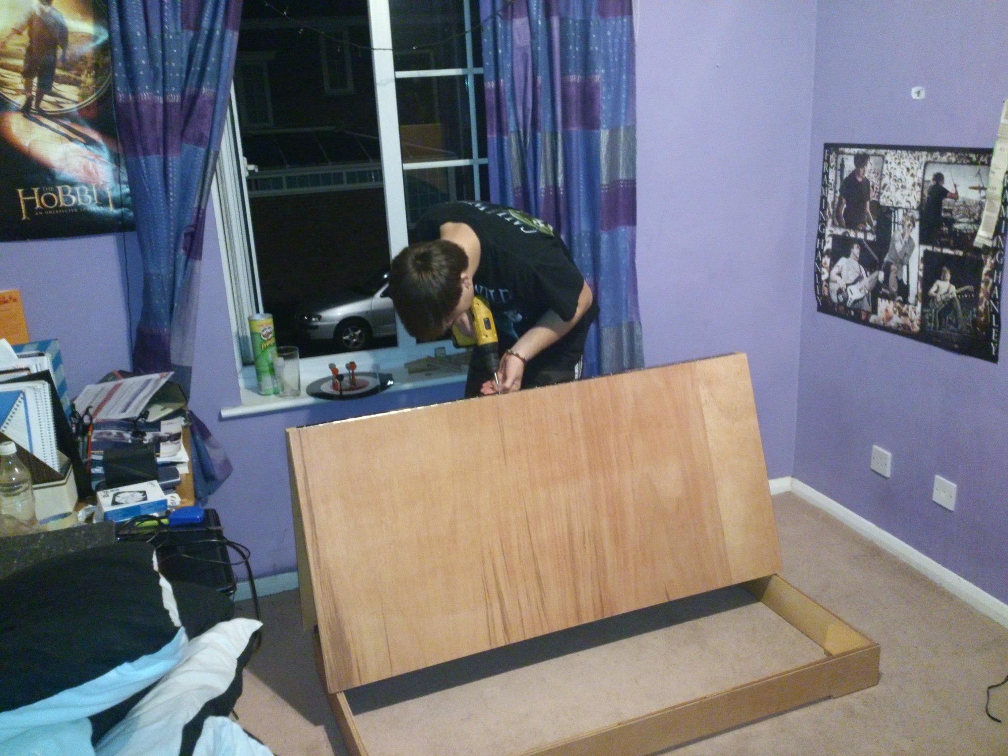
Material choice was a big one for this project, since the span of the boards was quite large and there couldn't be support beams along the sides with it being easy to fold. Solid wood would have been plenty strong enough but can you imagine how much that would have cost?! No the only choices were fibre boards or ply wood. In the end, 22mm 7 layer ply was chosen and the entire bed was made only of this, some hinges, screws and glue. The aspect ratio of the sheets meant that it wasn't economical to make each board from a single cut, and instead was spliced together from two smaller boards. The assembly of the bed was rather simple. We cut the wood into 3 sections, with the middle section being the longest and top being the shortest in order to achieve an angled back rest. The square base (storage box) was made separately. A reinforcing leg (see image on the right) was attached with screws from the top of the middle board. The decorative bottom leg was also attached from the top, and was assembled separately.
Miscellaneous
 and this put me out for the rest of the project sadly.jpg)
.png)
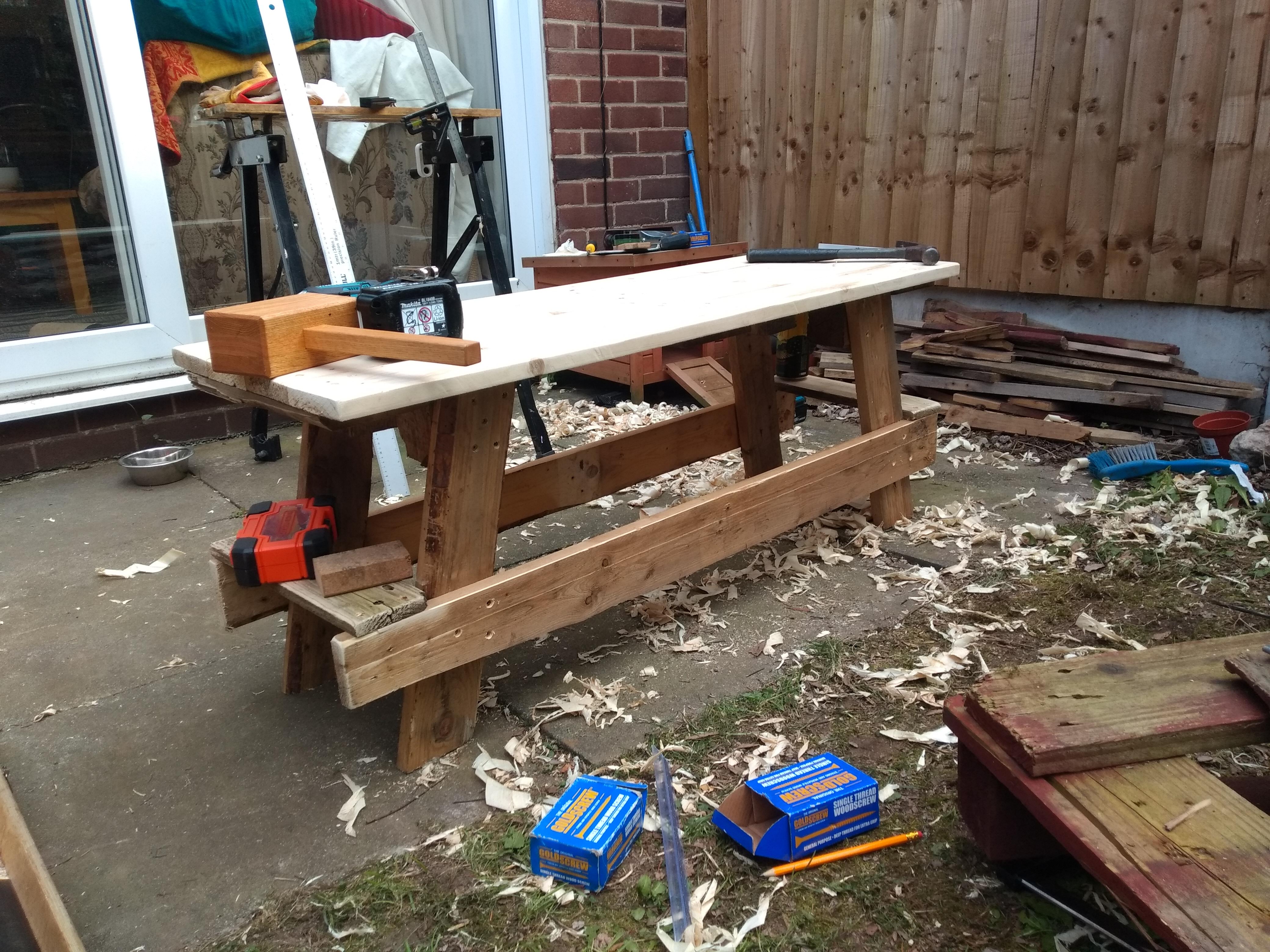
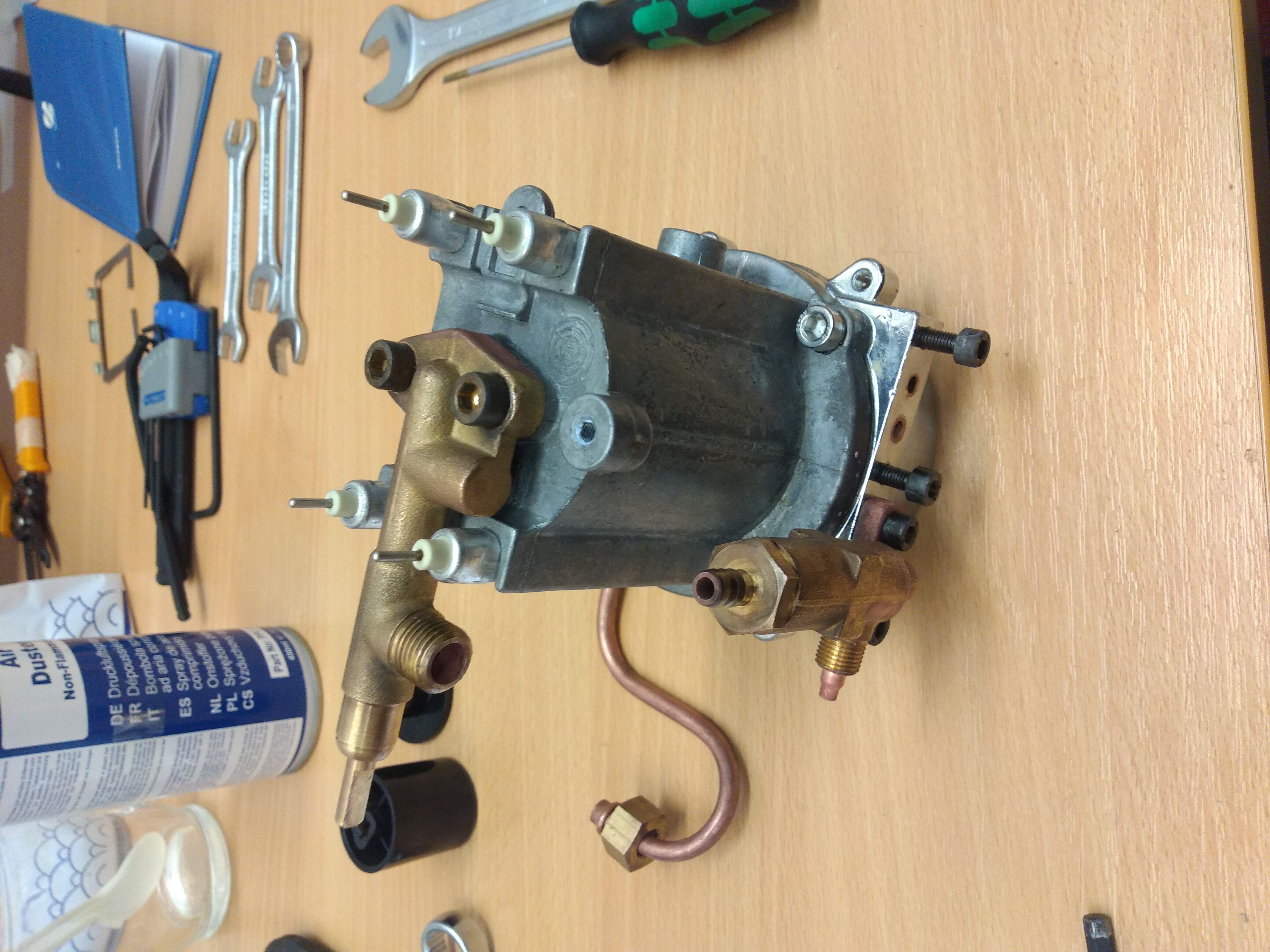
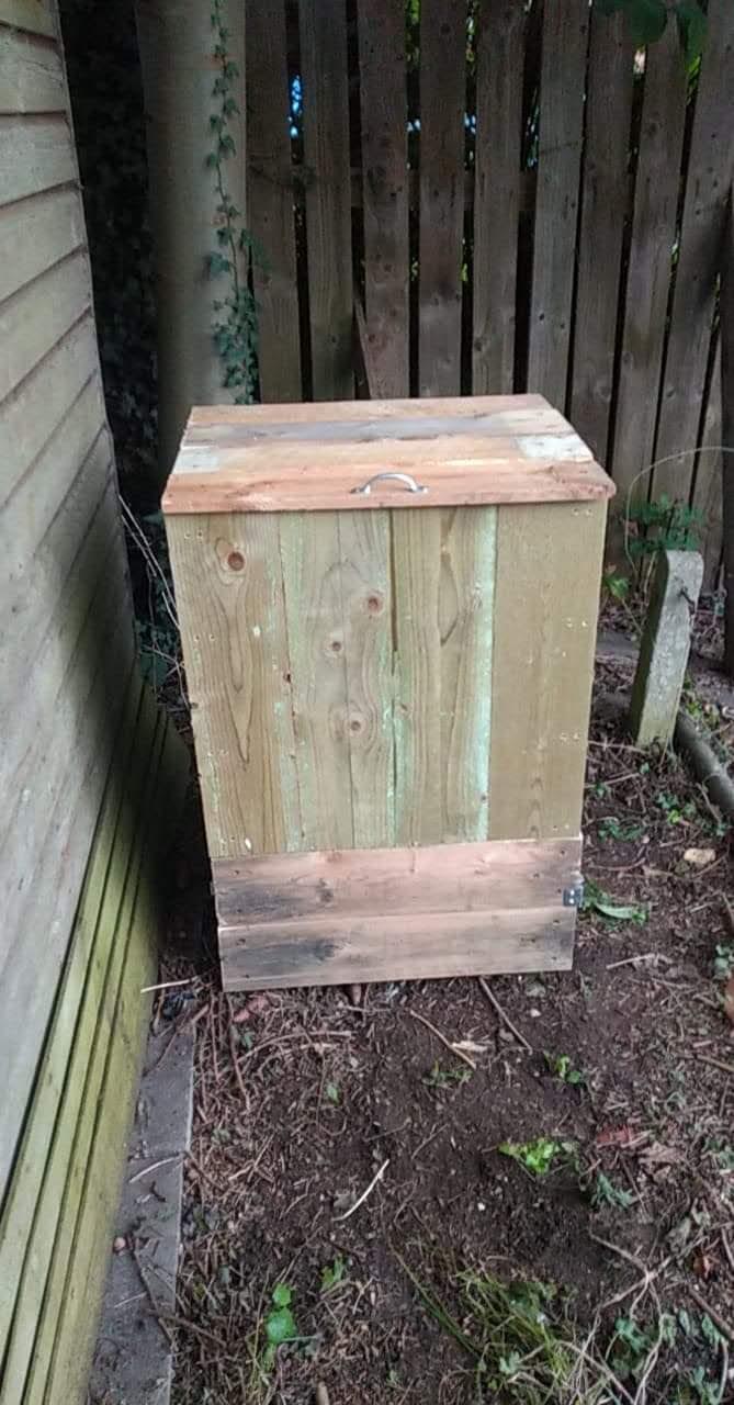
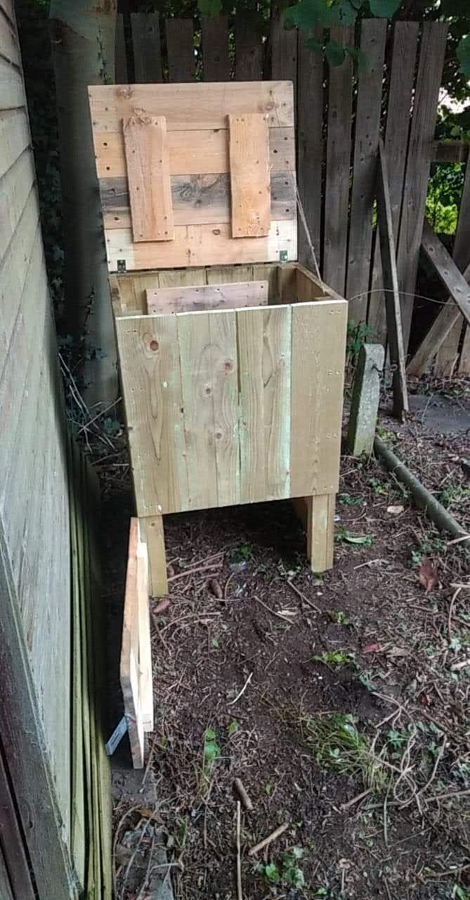
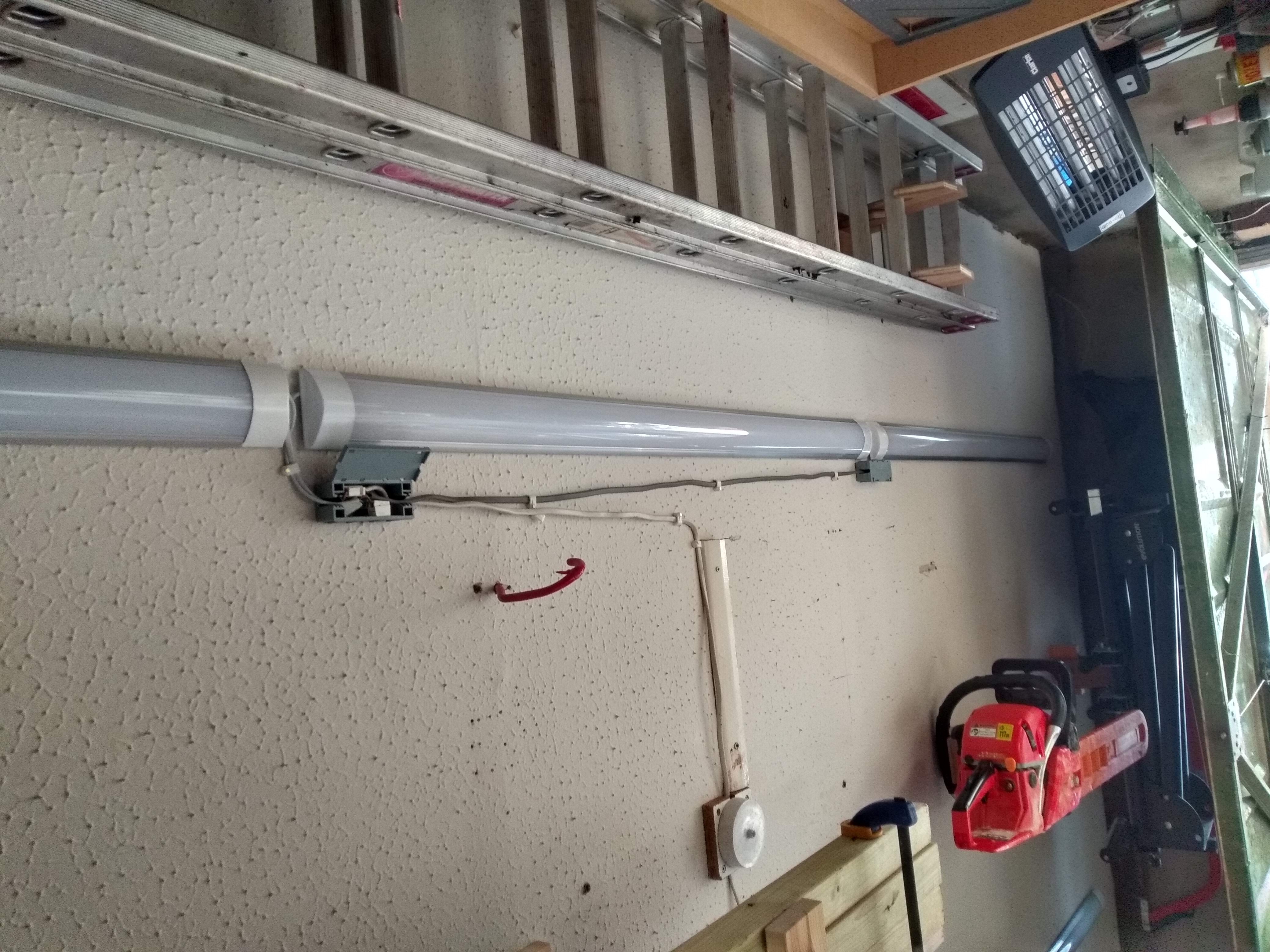
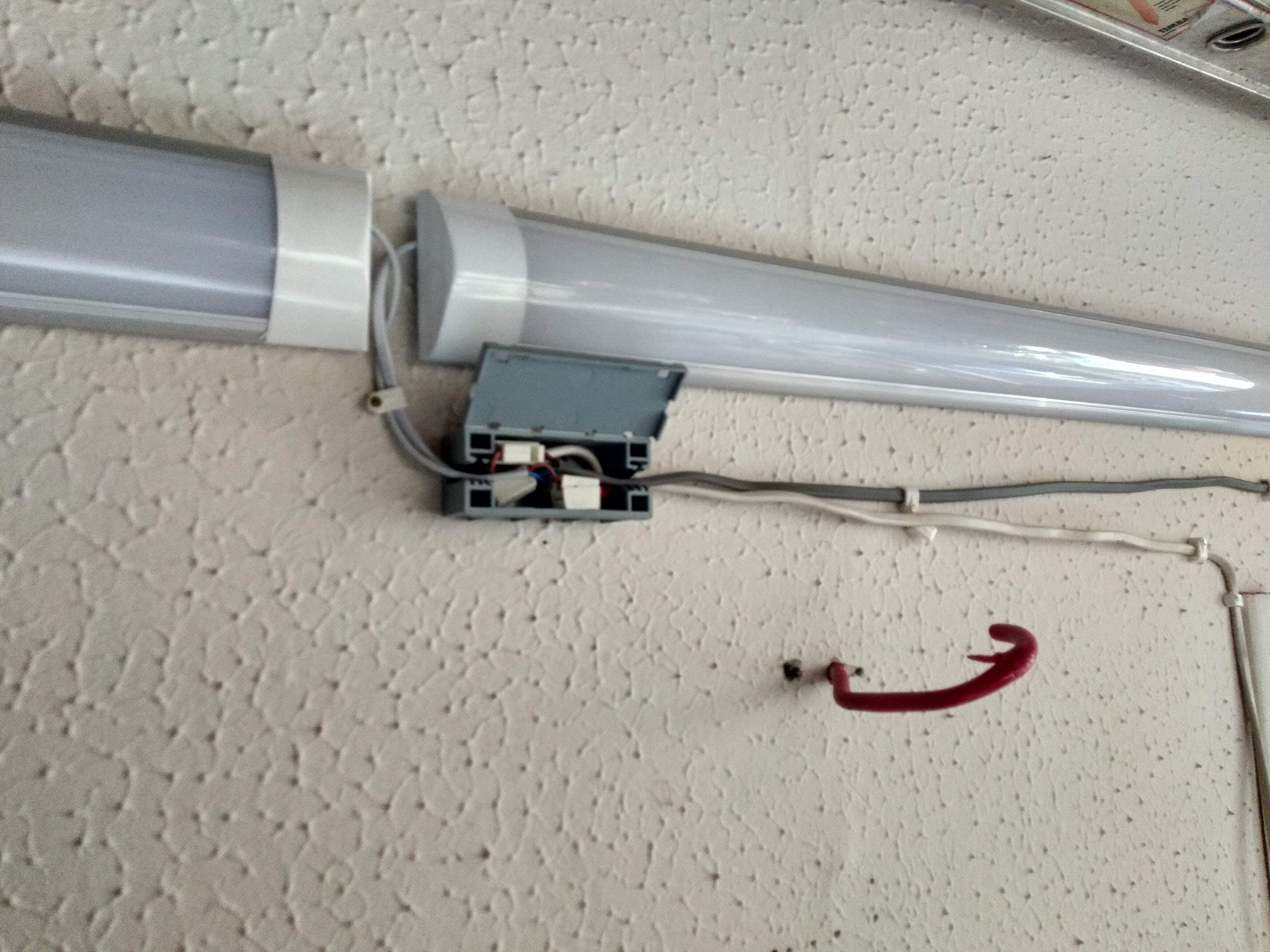
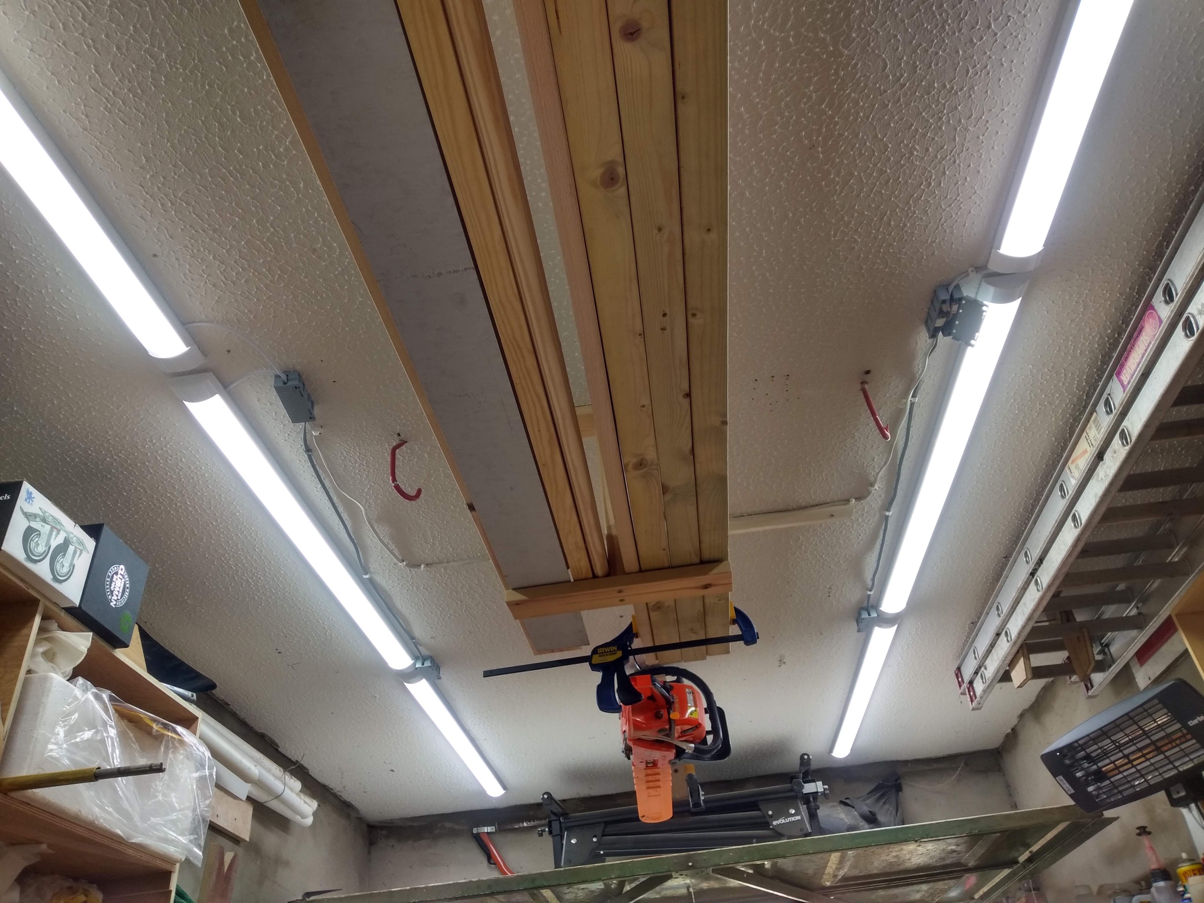
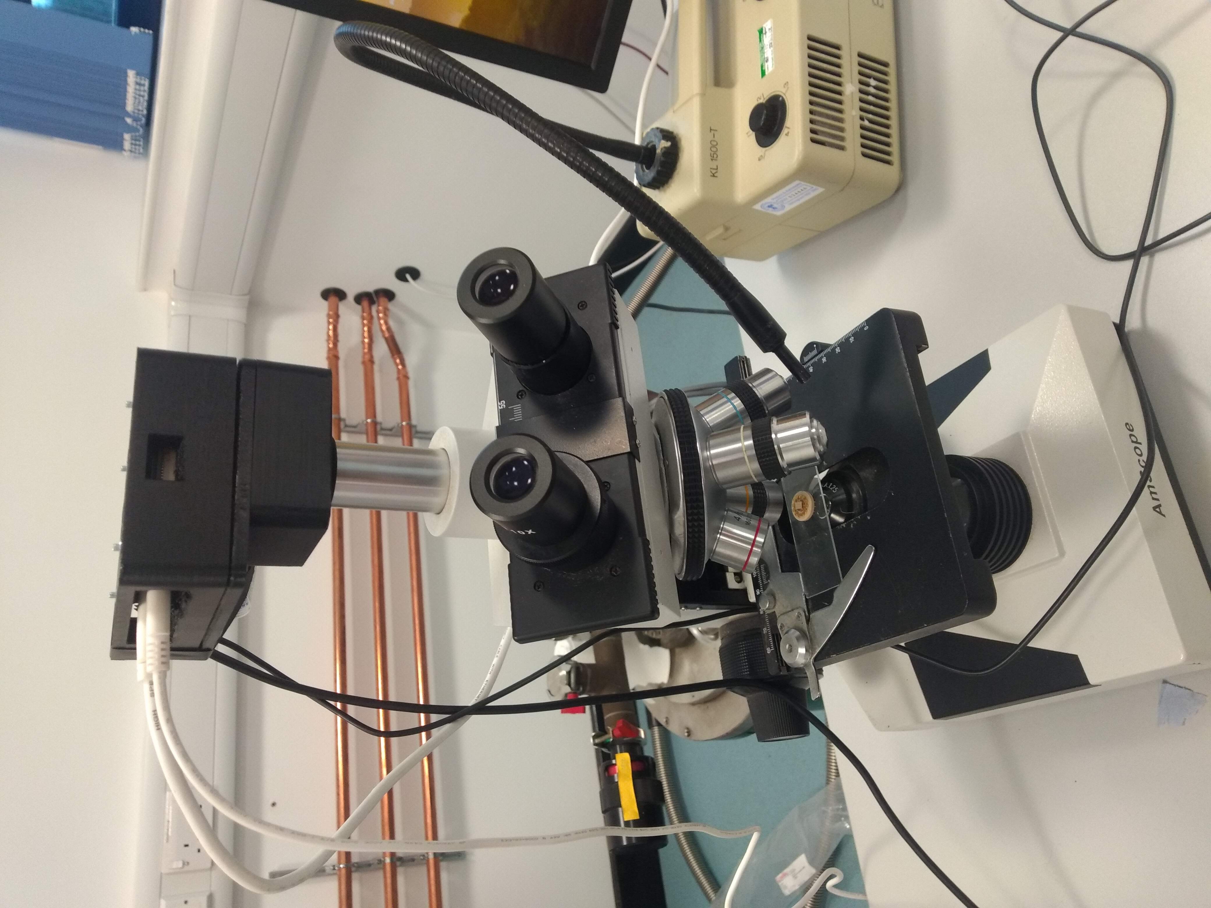
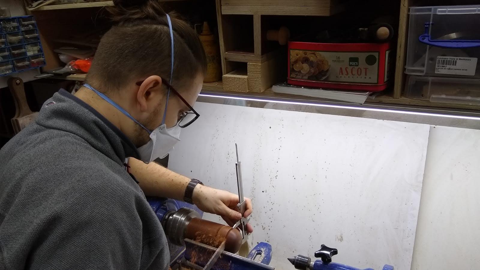
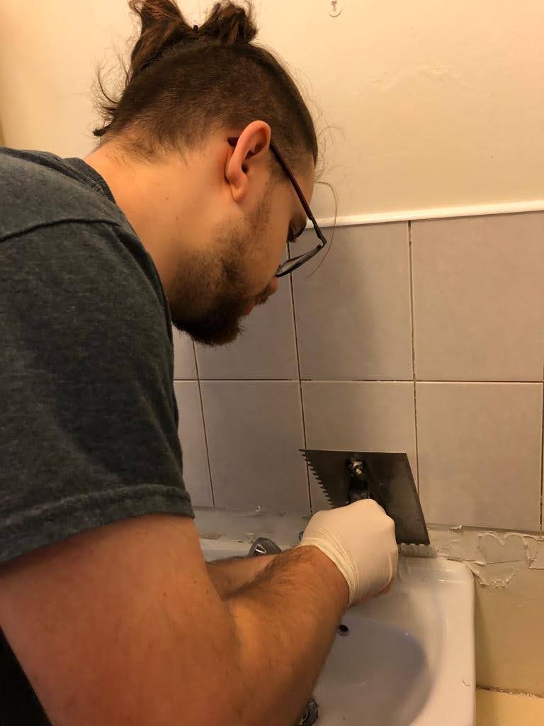
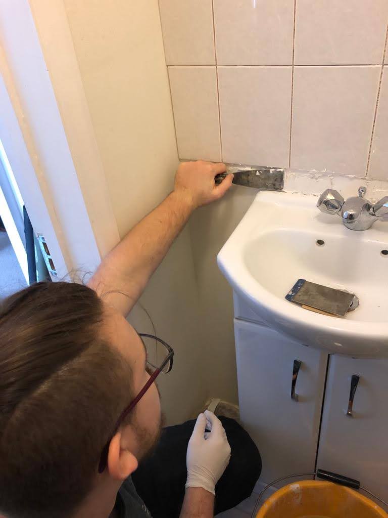
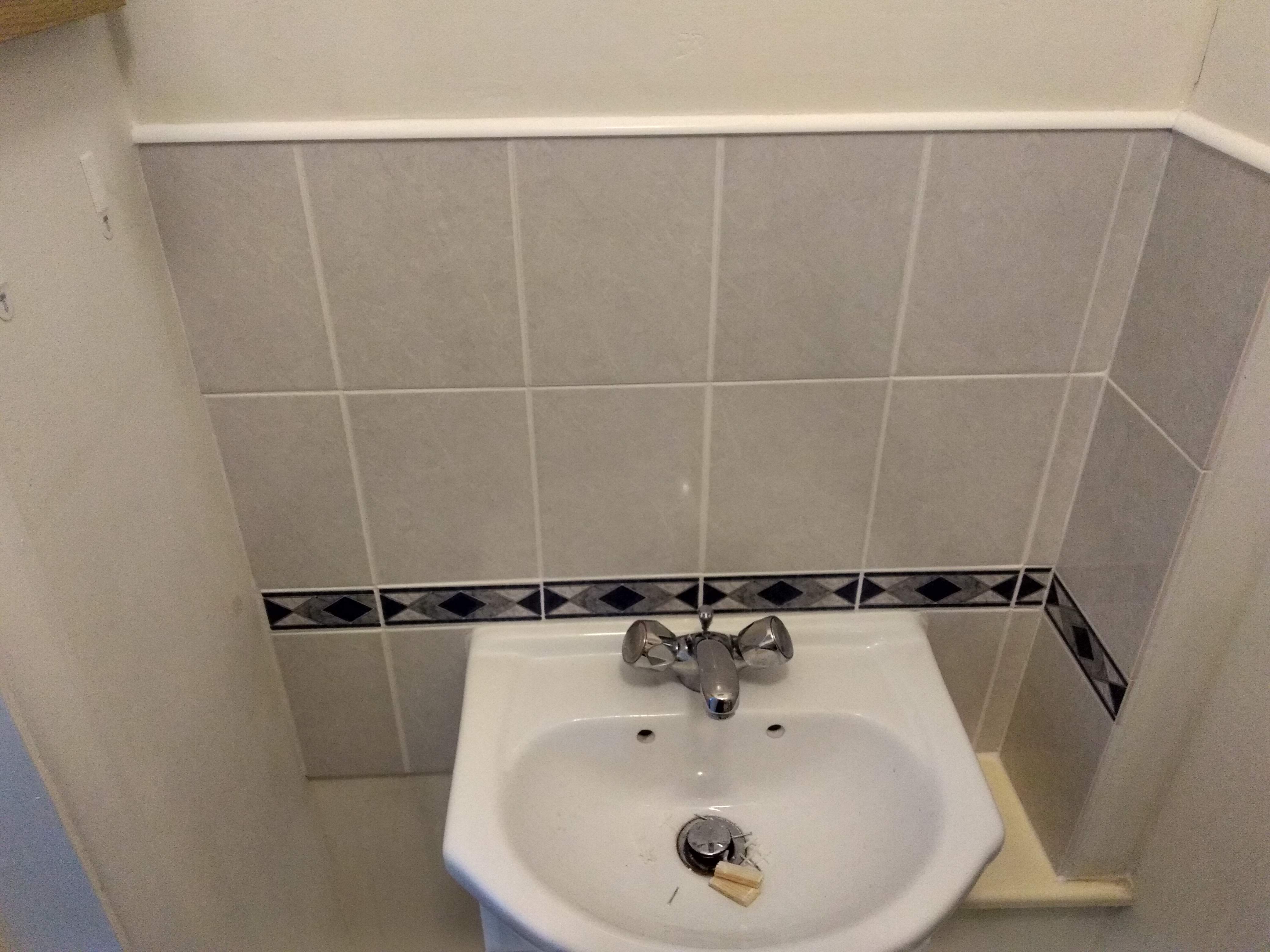
This is a collection of pictures from small, badly documented or undocumented projects that don't warrant a write-up by themselves.
Thank you for taking an interest.
If you are interested in further information about any of these projects or are interested in offering me a chance to apply to your comapny, please do not hesitate to contact me using the form below. If you would like to see a summary of my projects and interests, please visit the highlights page using the link below: