Dimmable Two Wire LED String Driver
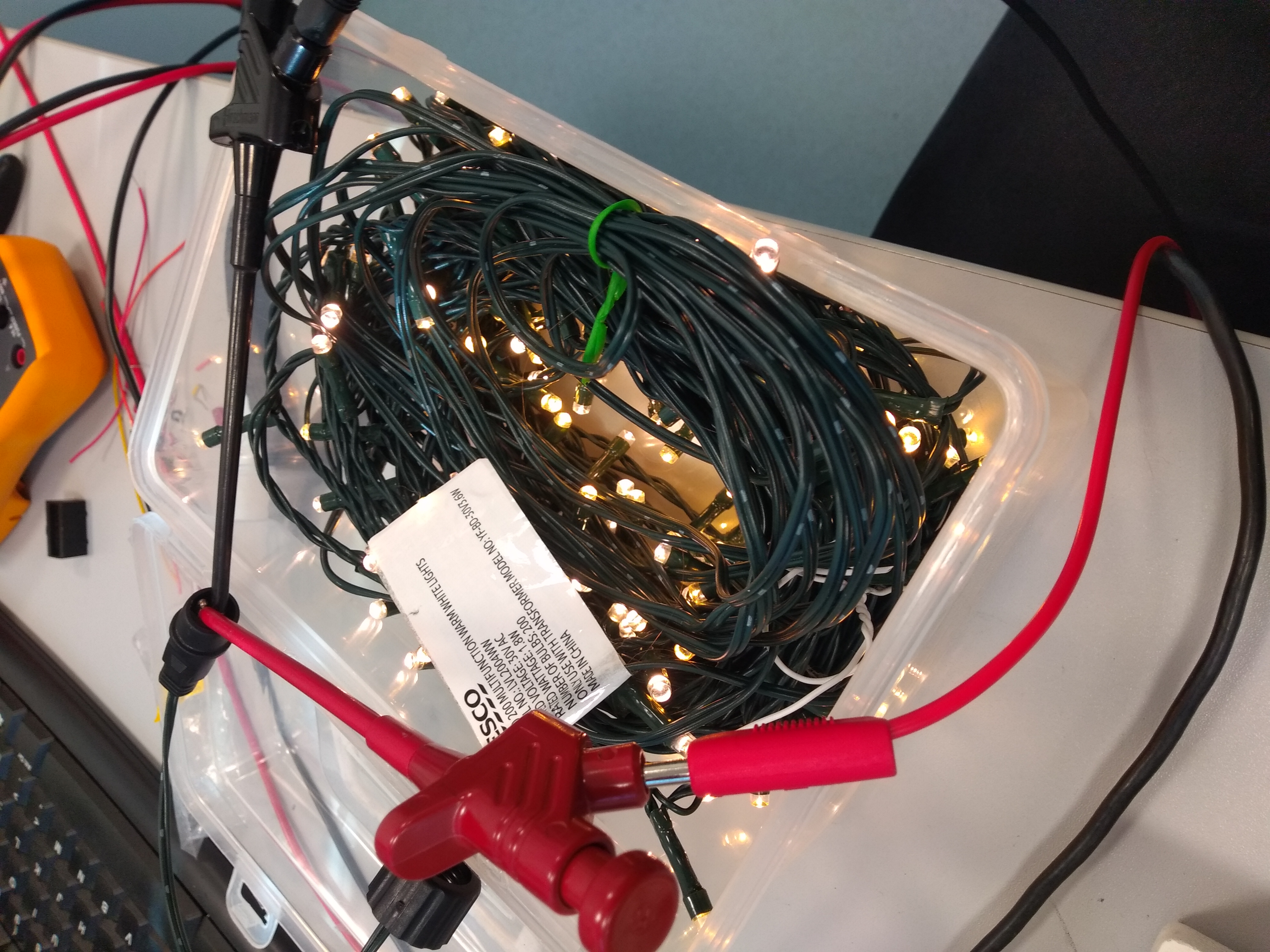
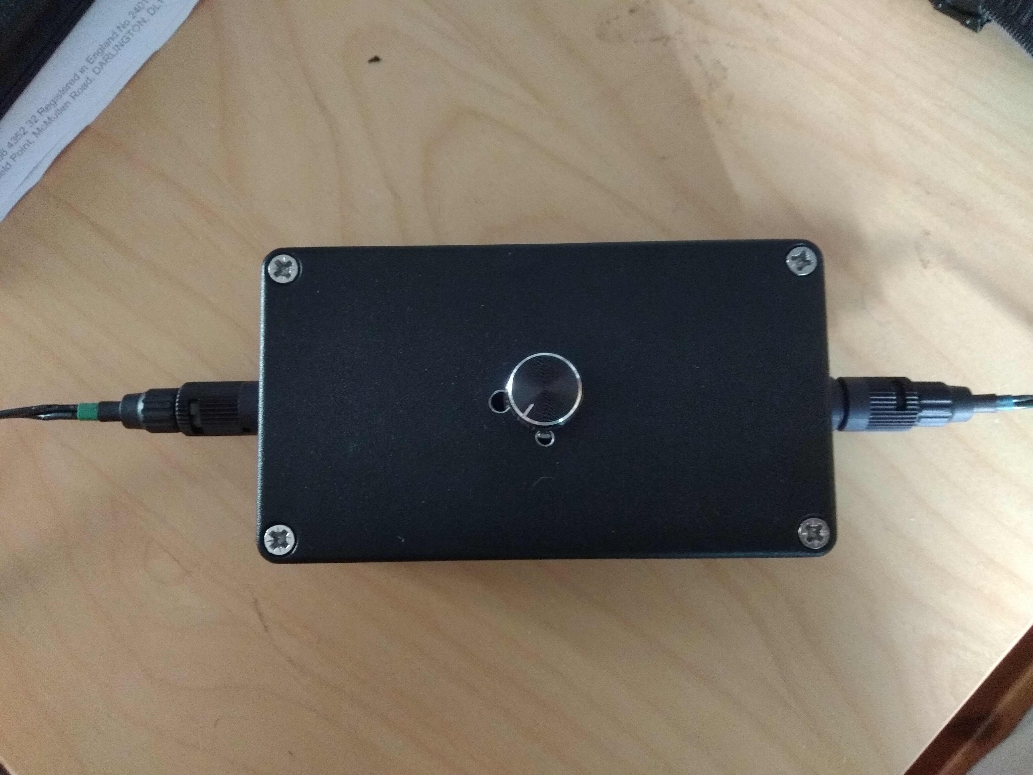
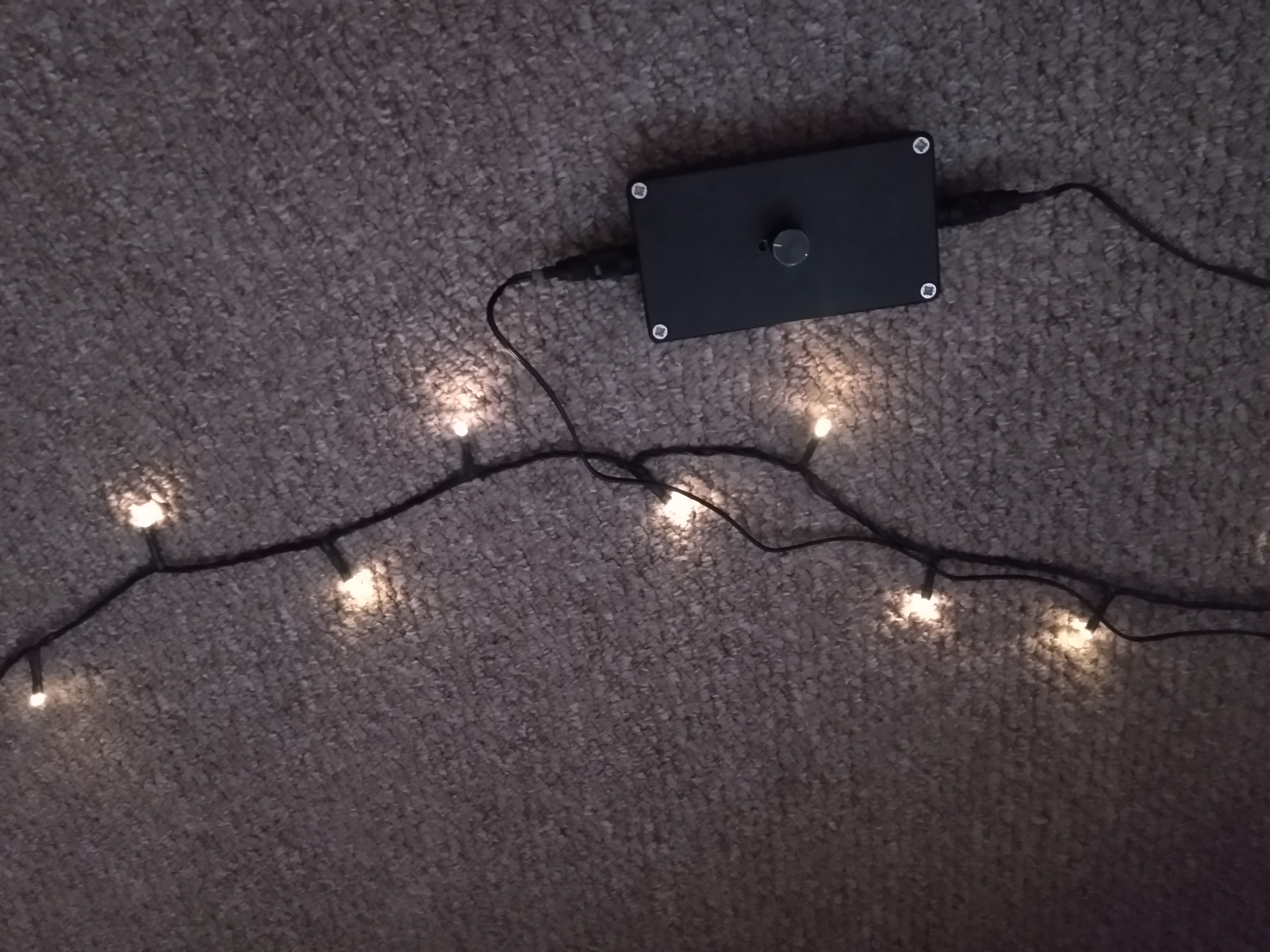
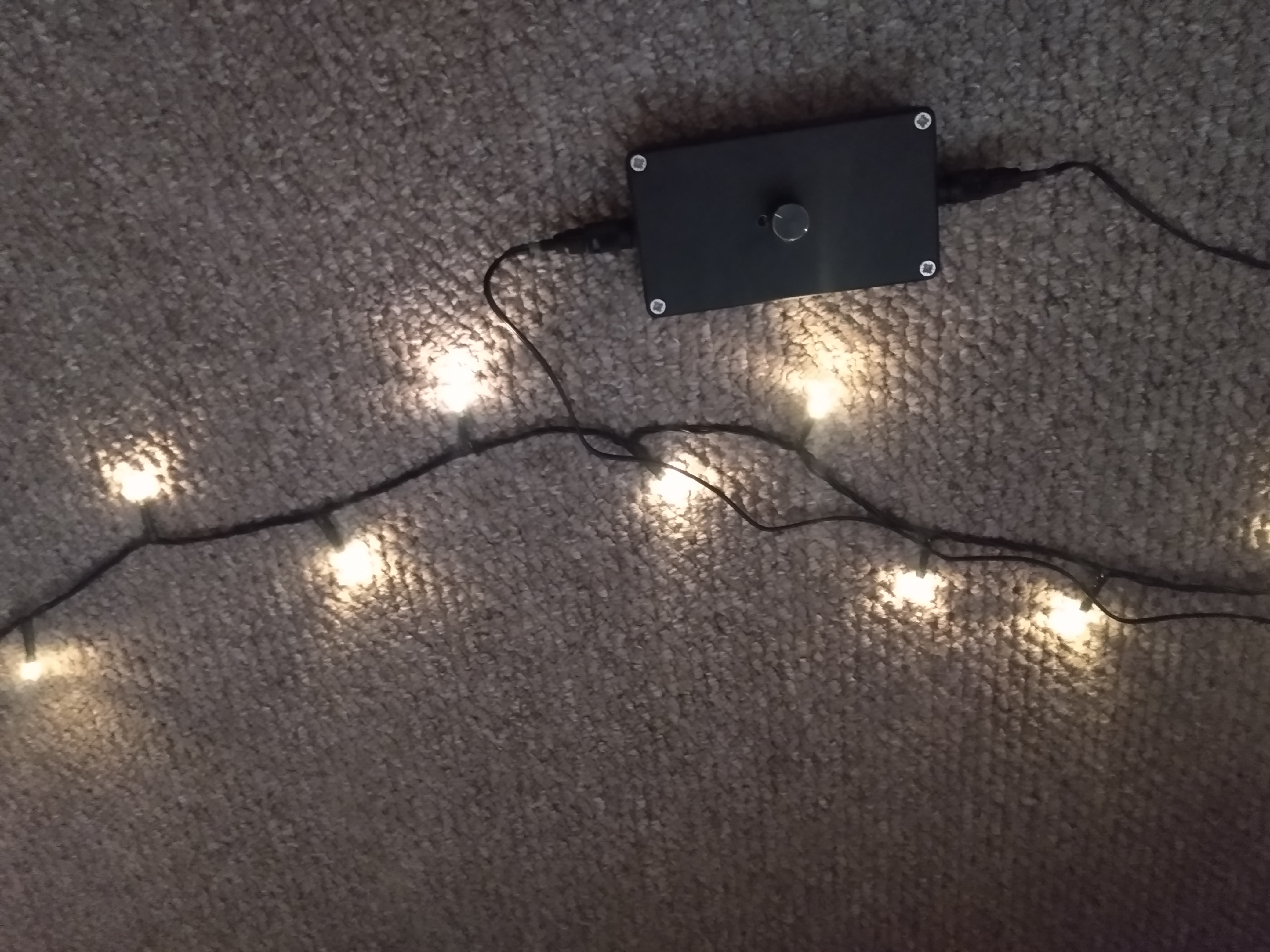
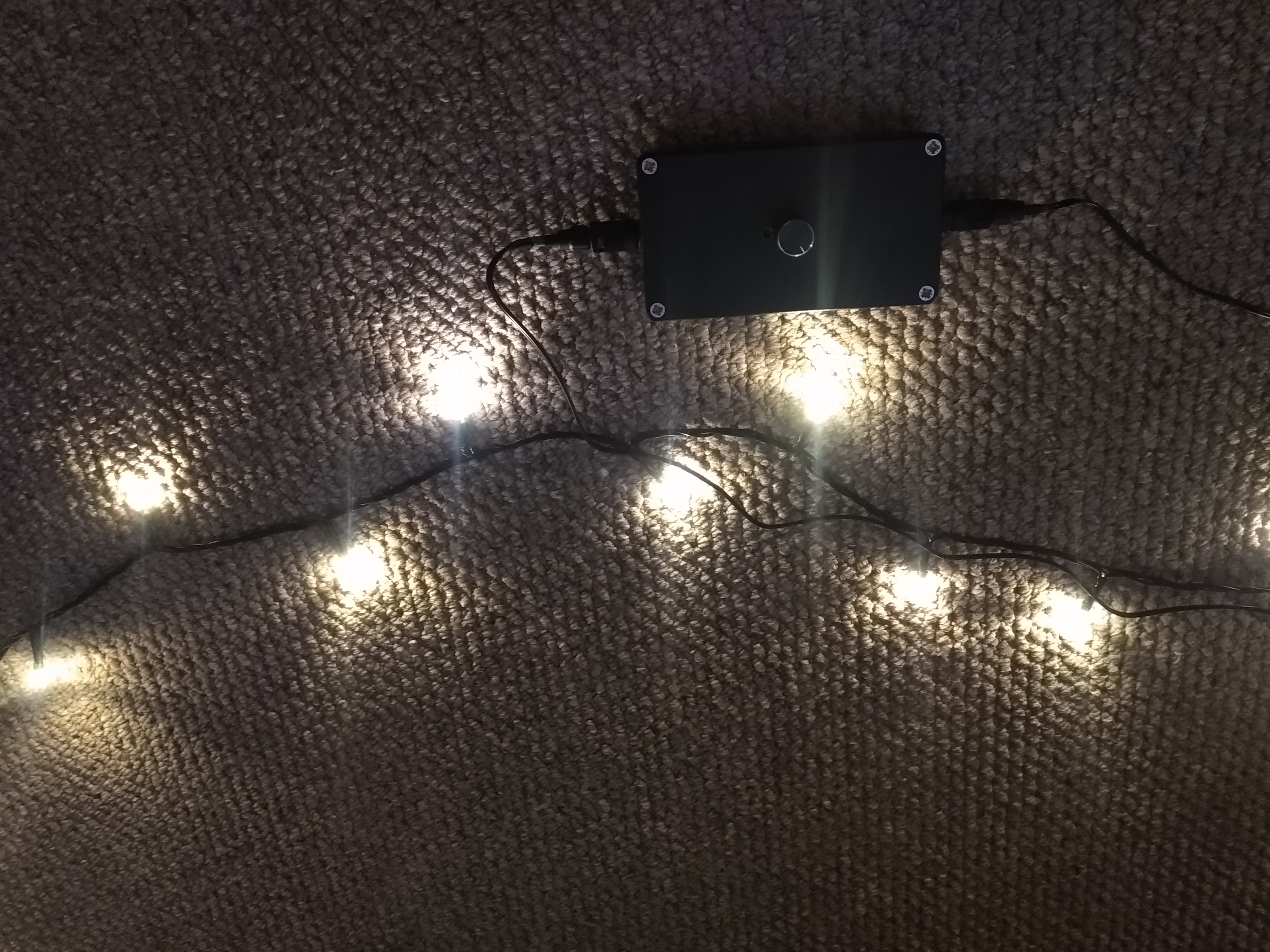
I bought some cheap fairy lights for my partner to use around a room to make the room feel cosy, unfortunately they it with the light of a thousand suns. I was worried they might, but I thought it would be simple to fix this with the addition of a resistor somewhere in the circuit but it turns out that these light are driver with two wires, not the typical three. For three wires, there is a ground lead and two separate control lines for each half of the lamps. For 2 wire control, the drive current polarity is swapped, with half the bulbs lighting with one current polarity and the other half with the other polarity (LEDs are Diodes after all). This complicates things because I want them all to be on and to be dimmer/dimmable. I decided to make a box with a knob.
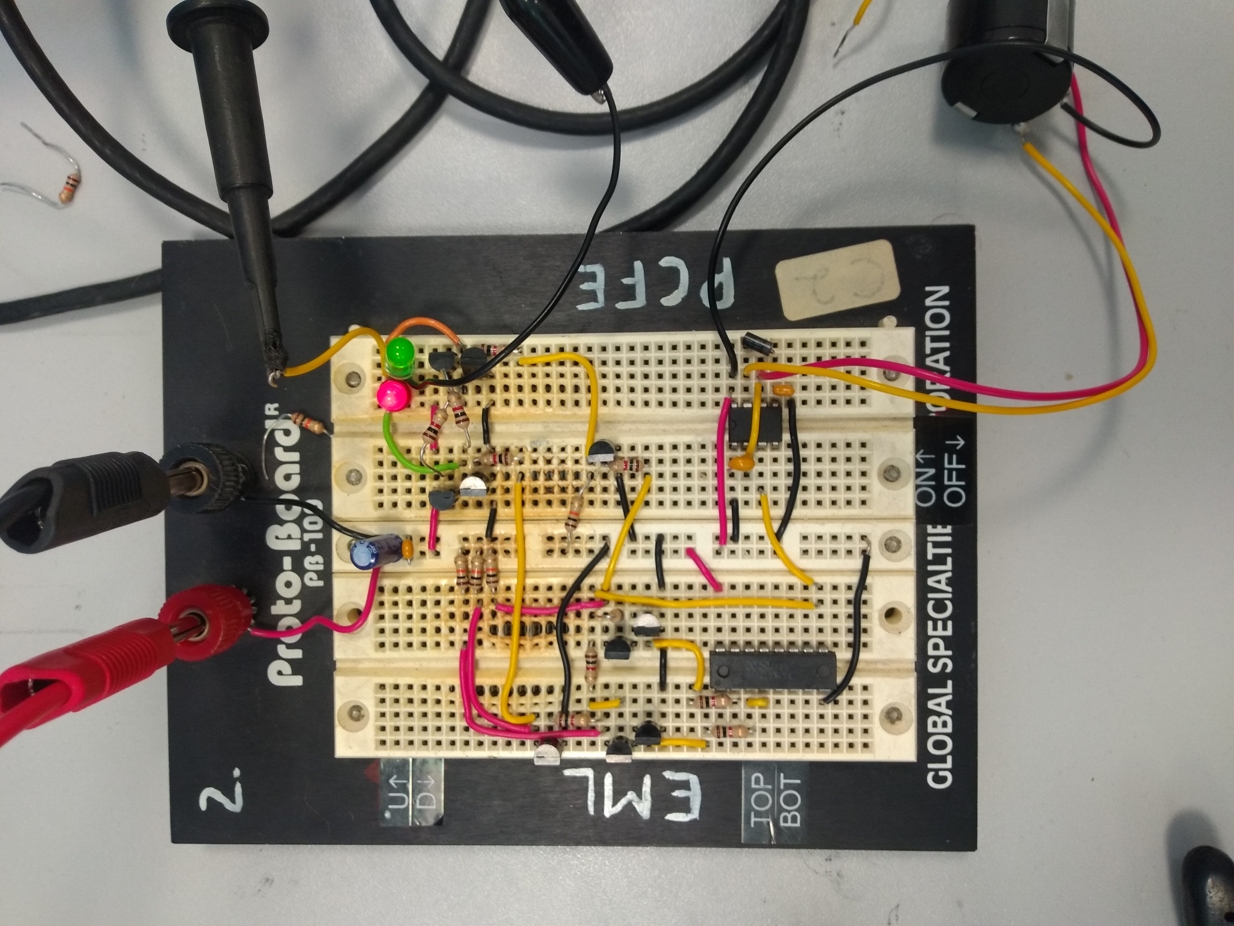
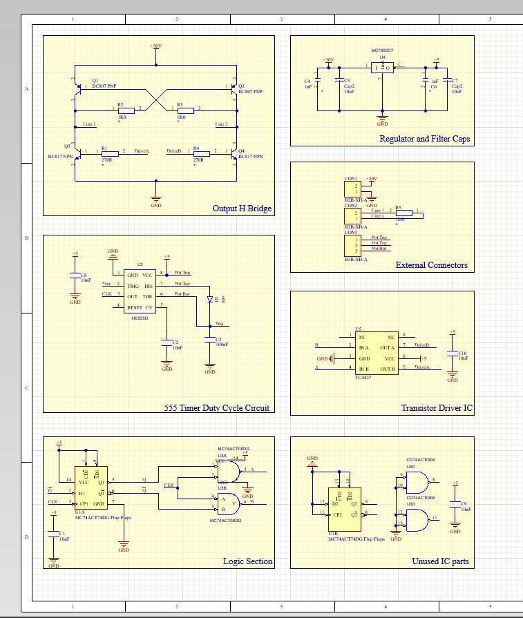
The circuit diagram is available below. The circuit's goal is to drive the LEDs in a way such that all the lamps are lit, and each channel is dimmed equally. A PWM signal with alternating polarity is the goal. To achieve this, we need an oscillating signal, preferably a square wave, which can swap between two polarities. I found that the original circuit for a very similar power supply used an H-bridge as shown in this diagram from this post. I can source all these parts easily, I only need to solve the DRV1 and DRV2 signals which must never both be on. To do this, a 555-timer in a constant period configuration was used, with a potentiometer to control the duty cycle. The resulting clock signal is passed to a toggle latch and a pair of AND gates, such that DRV1 is high when the latch Q is high AND the clock is high, and low otherwise. Similarly, the DRV2 signal is high when latch Q AND the clock is high, otherwise it is low. The 555 timer therefore controls how long the current is flowing and the latch controls the polarity of the current. The 30V supply will be external and a 5V linear regulator will be used to provide supply voltage for the logic.
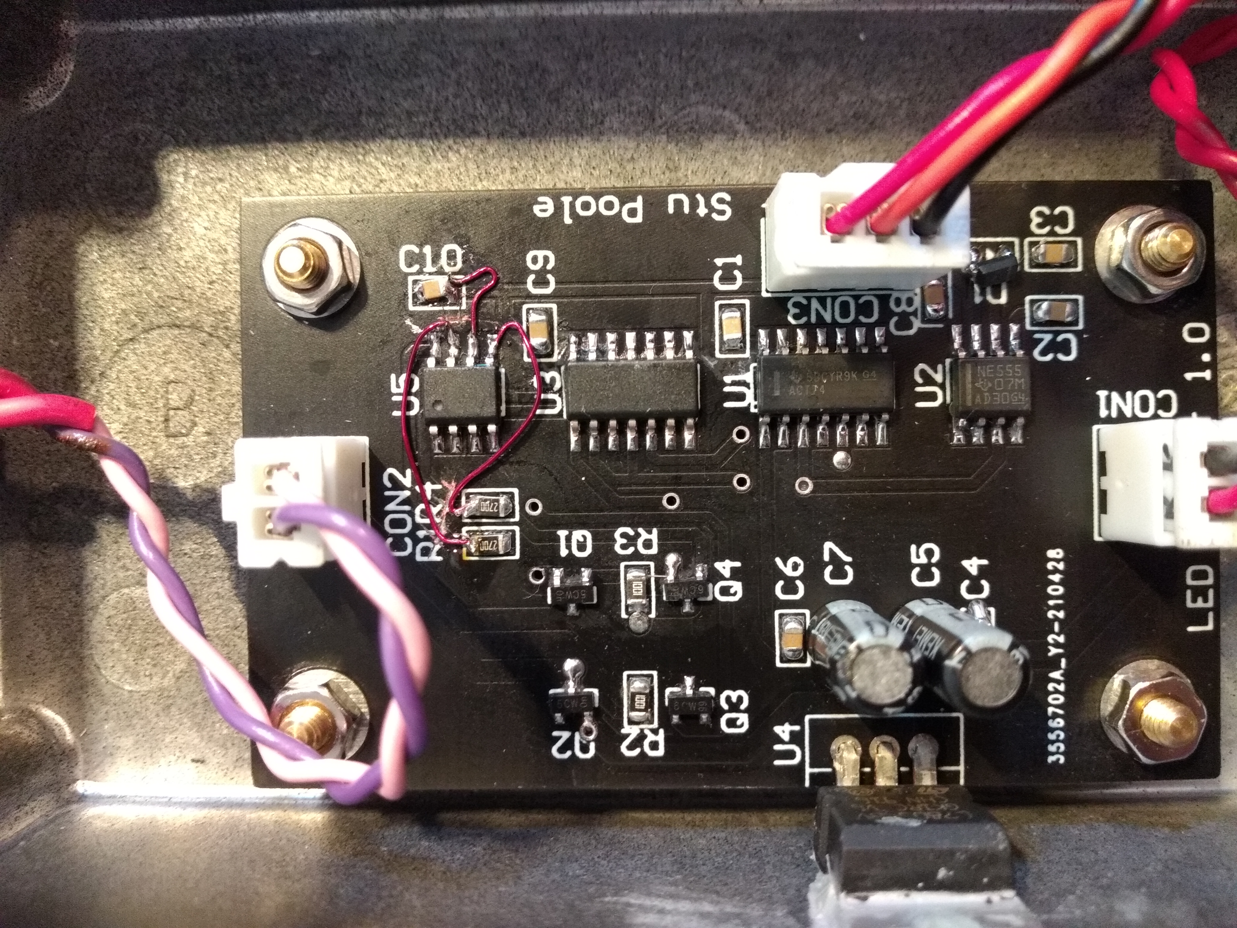
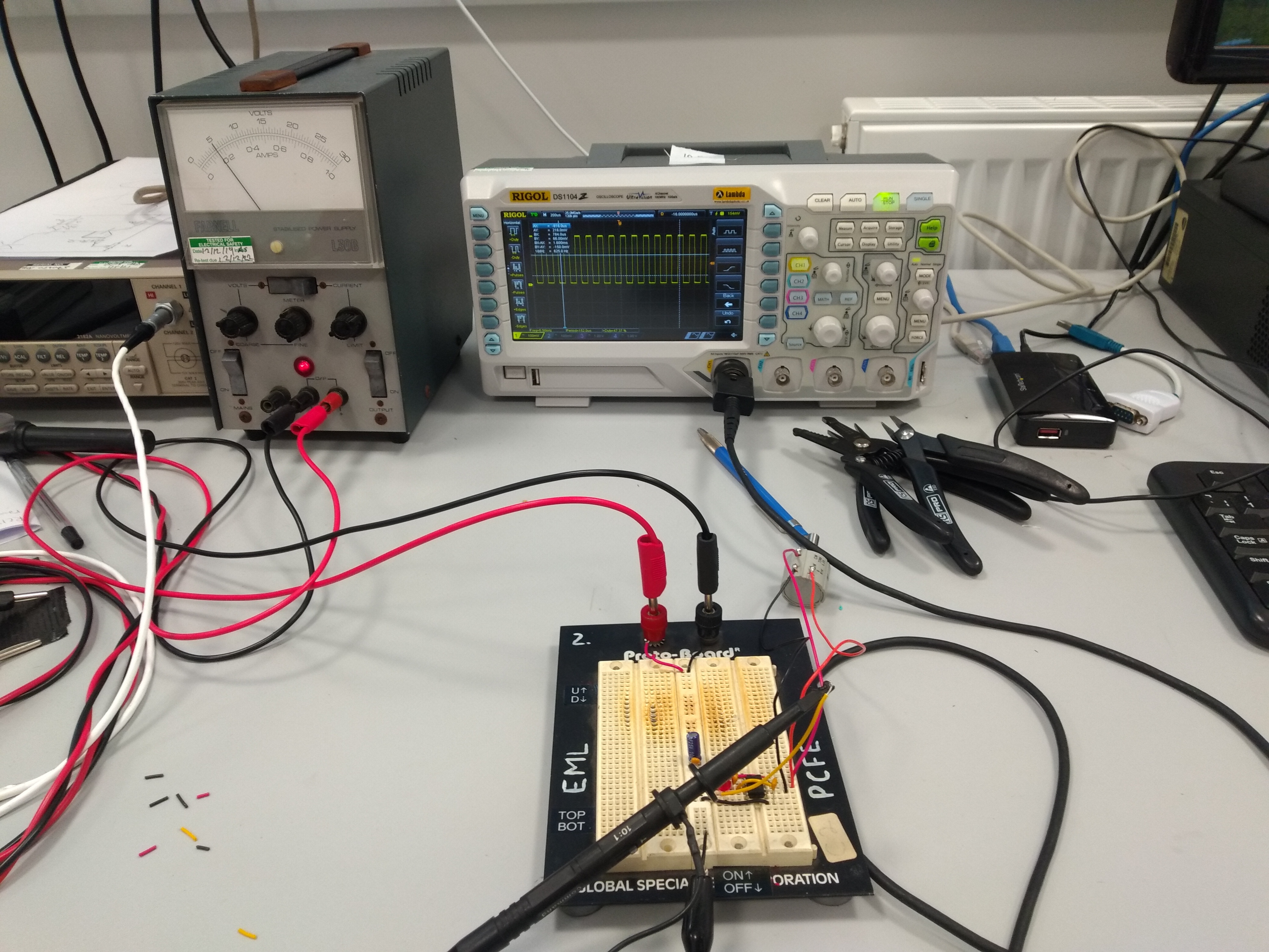
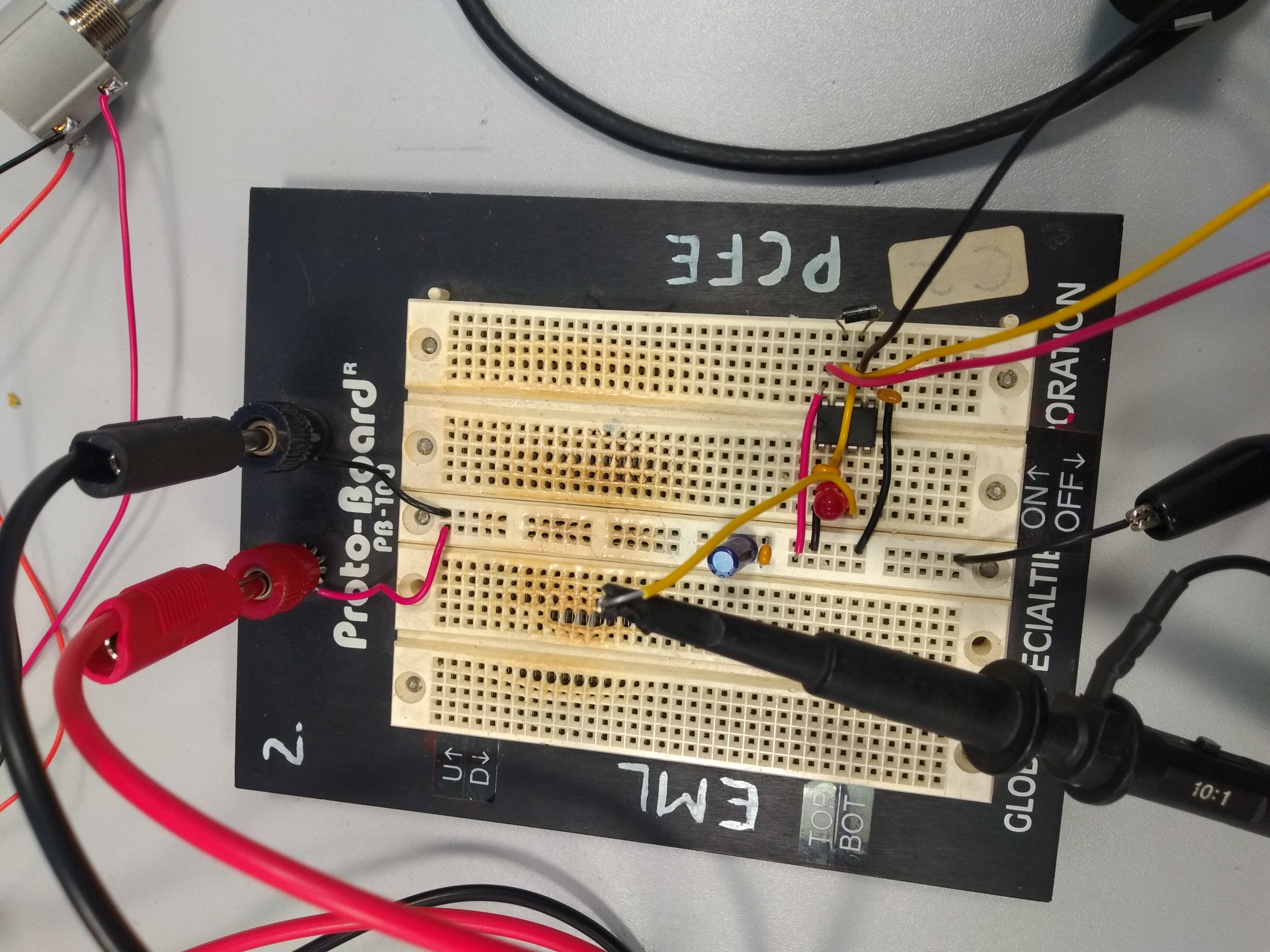
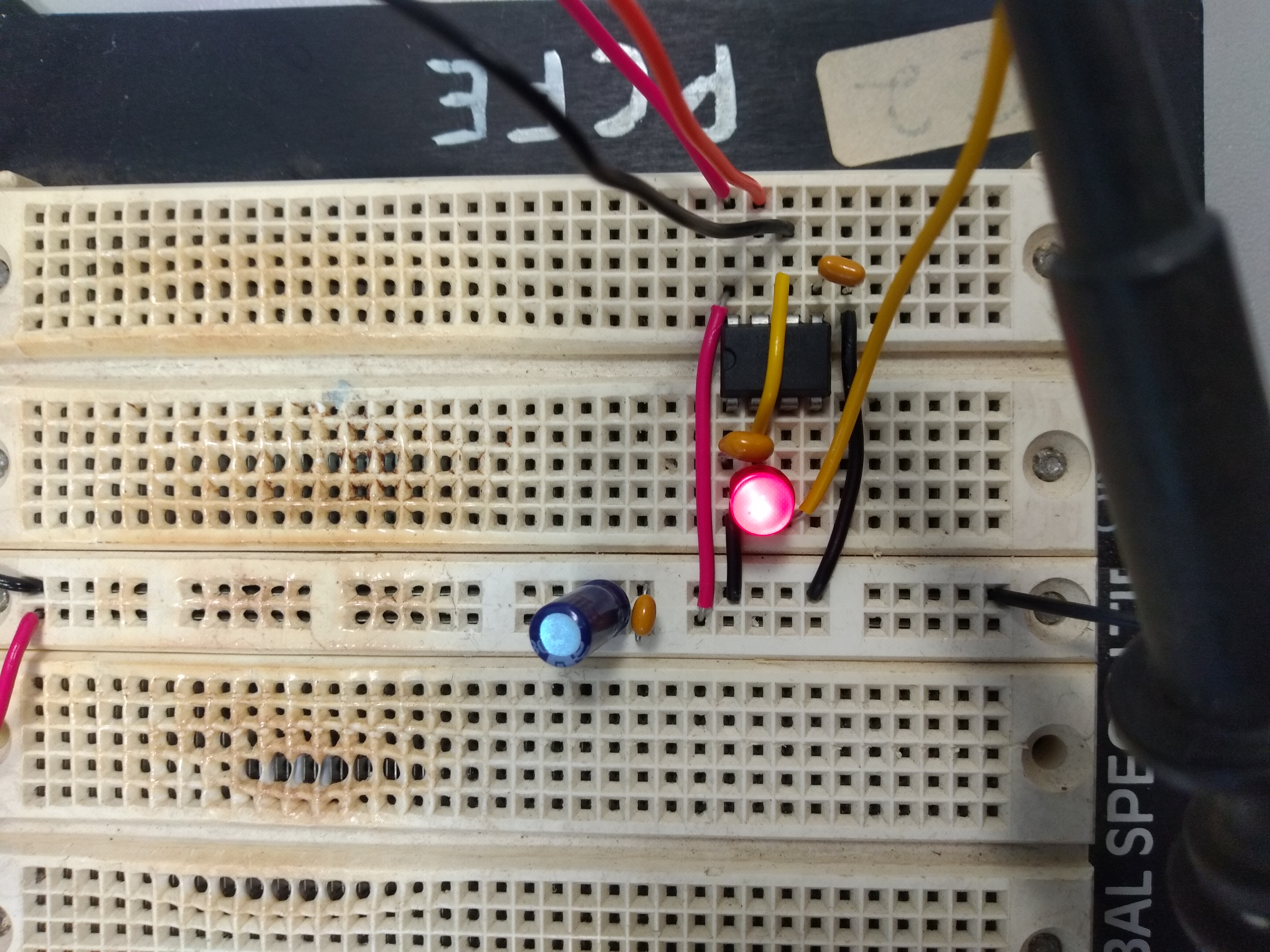
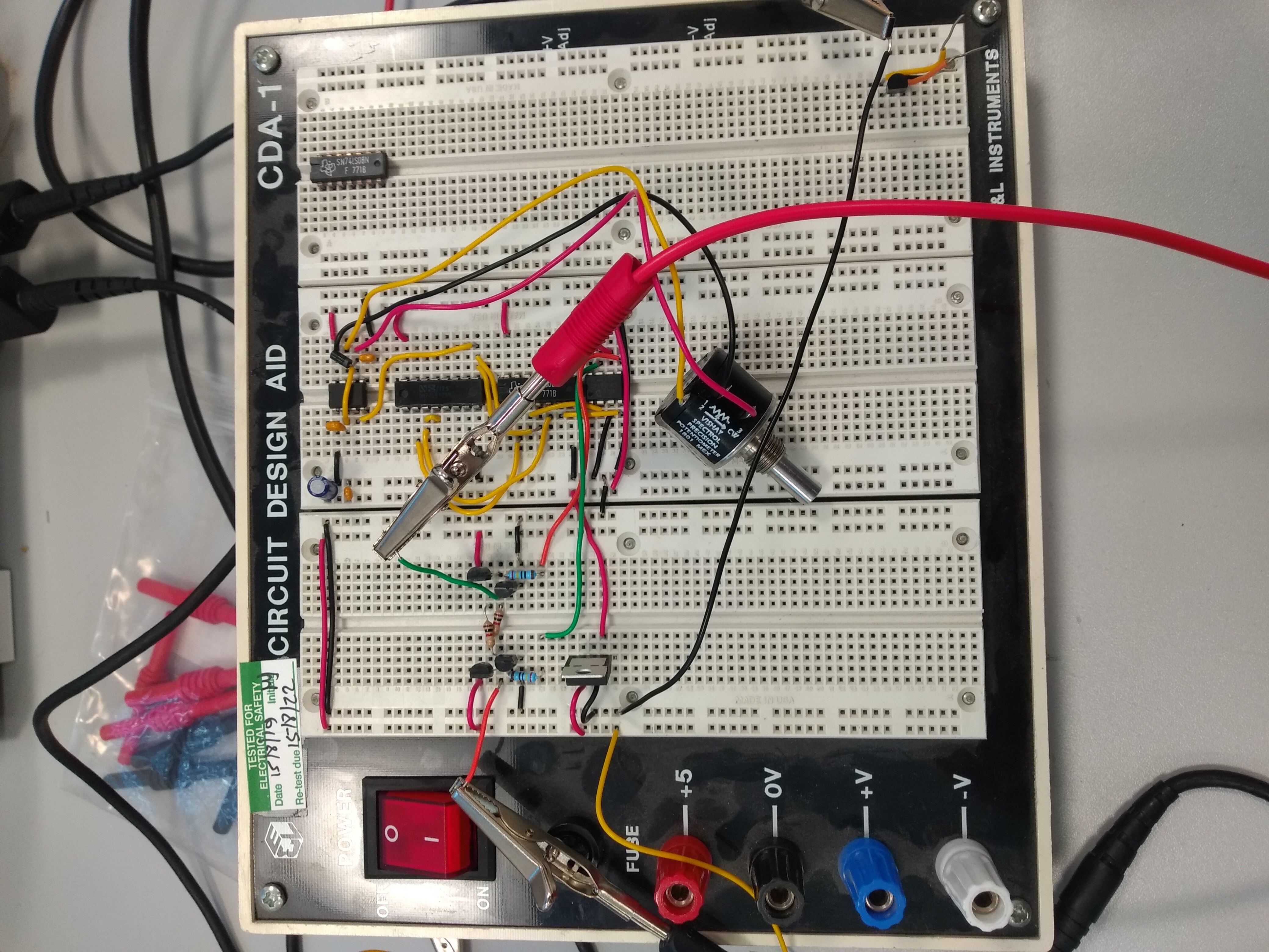
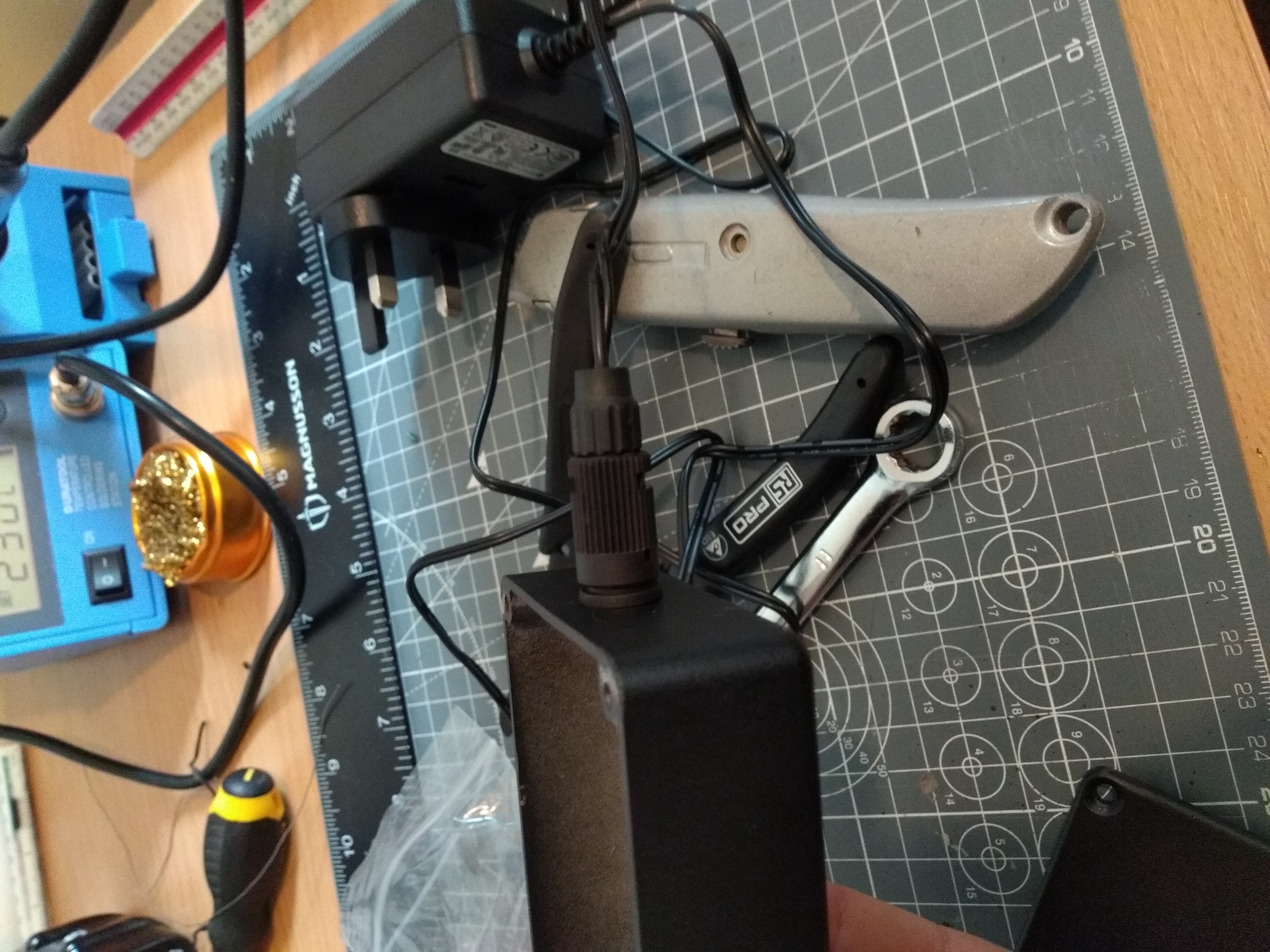
To make the circuit, I first prototyped it on a breadboard. At first I tried to make all the logic with discrete NPN transistors (because I have a very large pile of them) but this became much more difficult than expected and I could not get the circuit to drive (any mistake down the line would blow up a transistor and I'd have no idea what caused it). Therefore I borrowed some DIP versions of the chips used in the SMD version. After a proof of concept was shown to work on a few small LEDs, I hooked it up to the led chain and quickly found that the regulator was searingly hot. I had not realised that the specific version of the and gates I had were only able to source a few milli-amps. This meant that the transistors did not saturate and therefore were highly resistive. I had a 2-channel MOSFET driver IC on hand and decided to use that to source the current. This worked well.
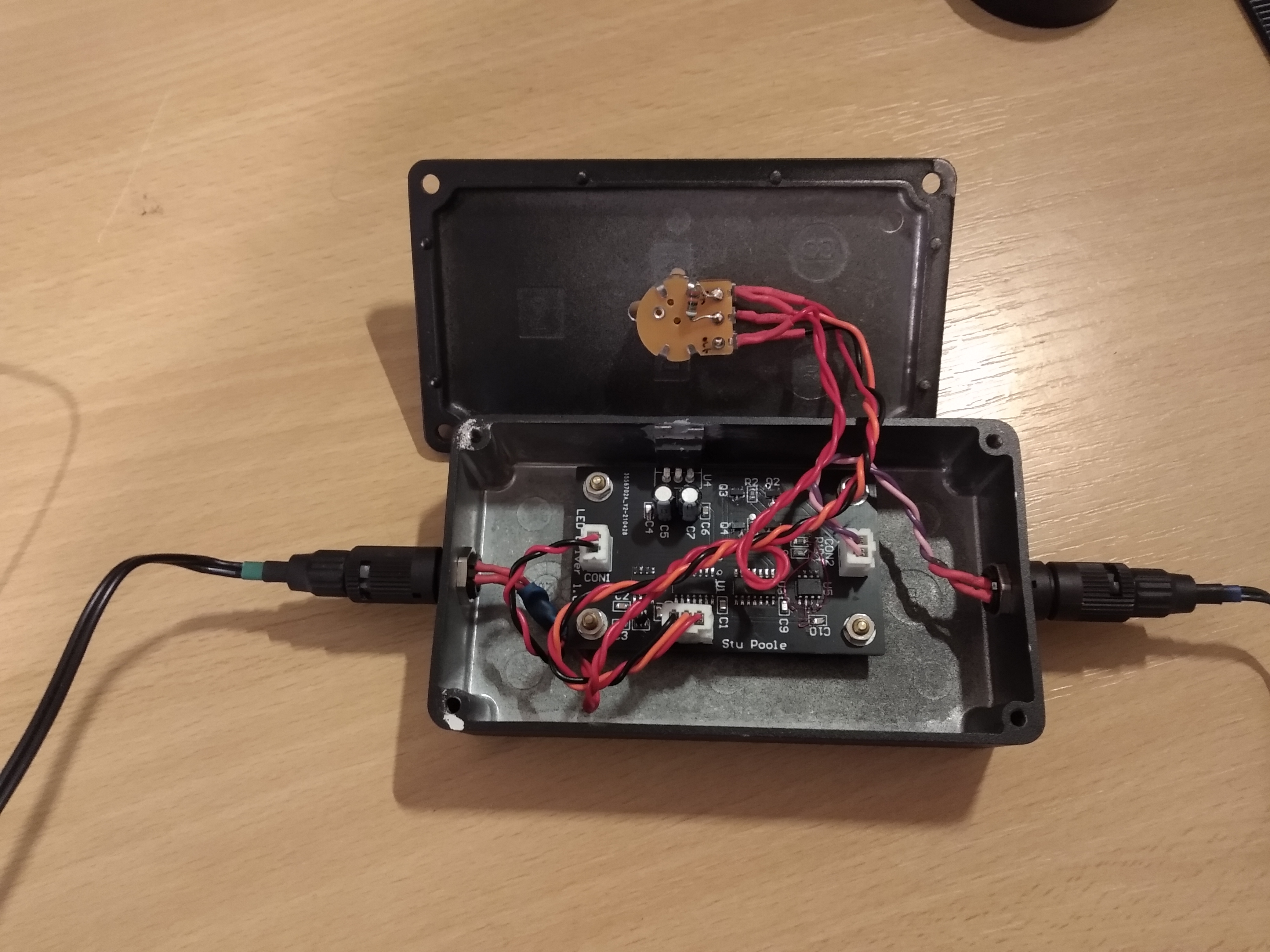
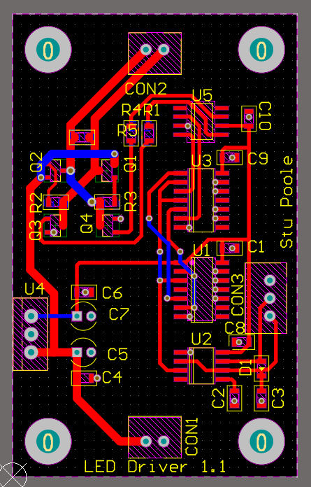
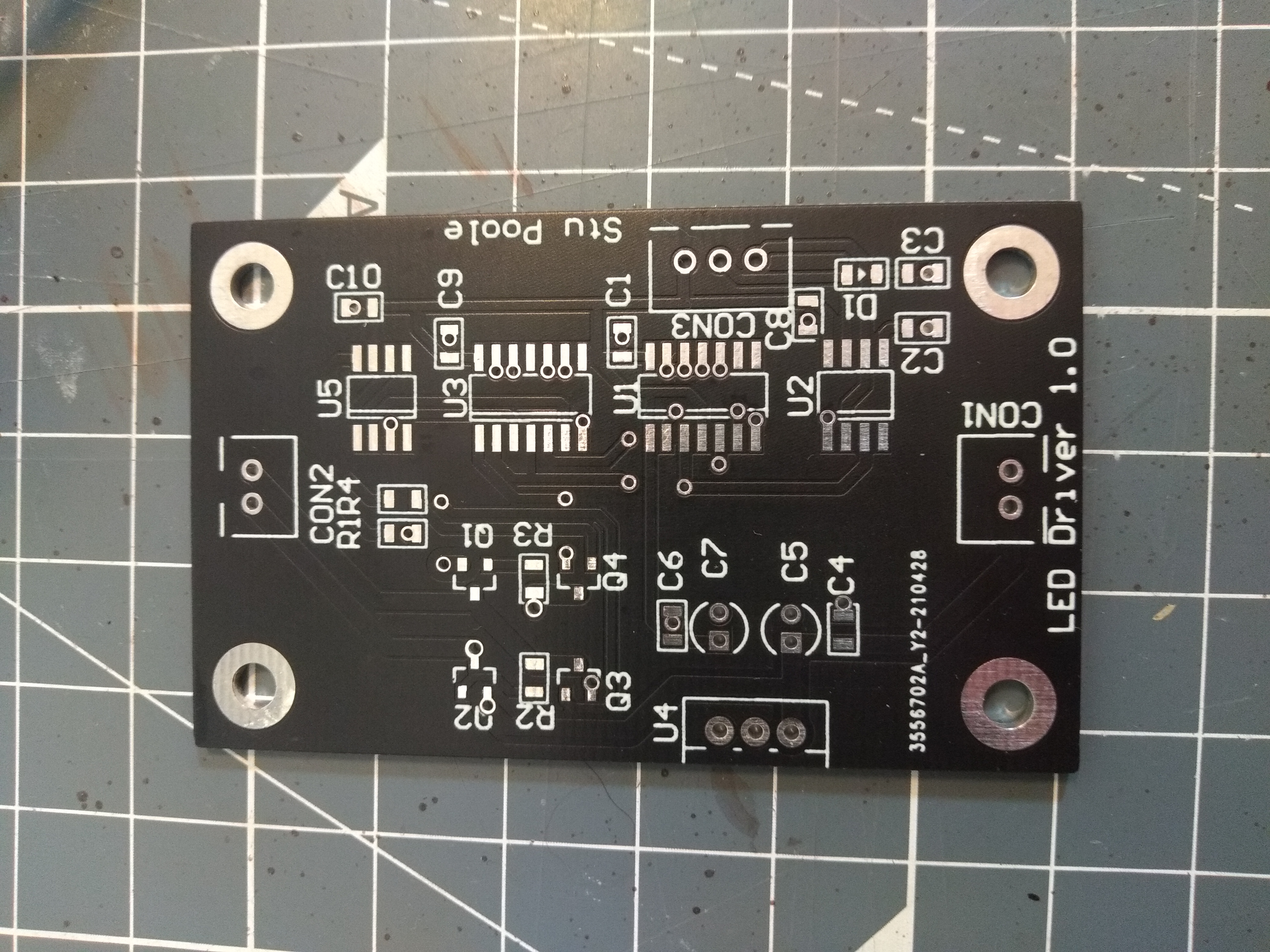
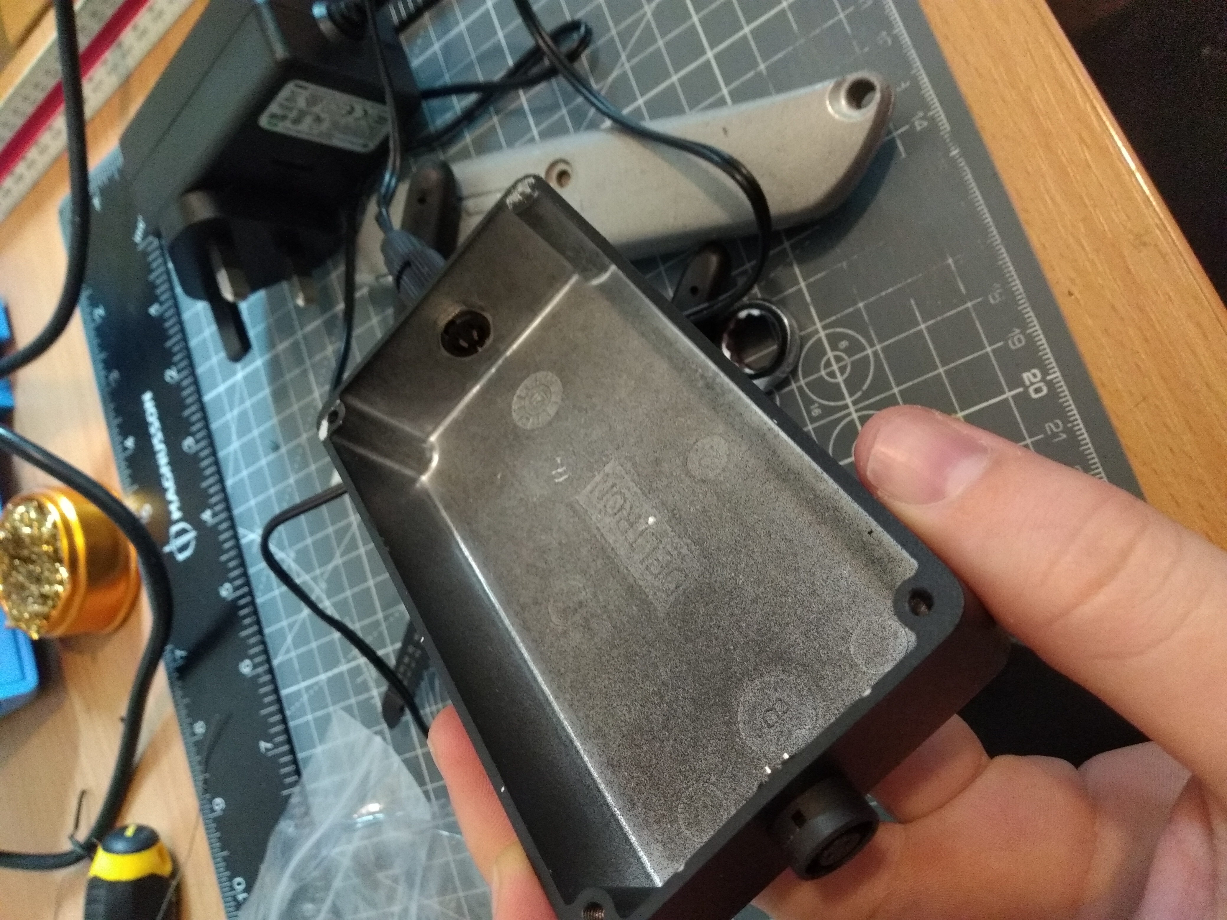
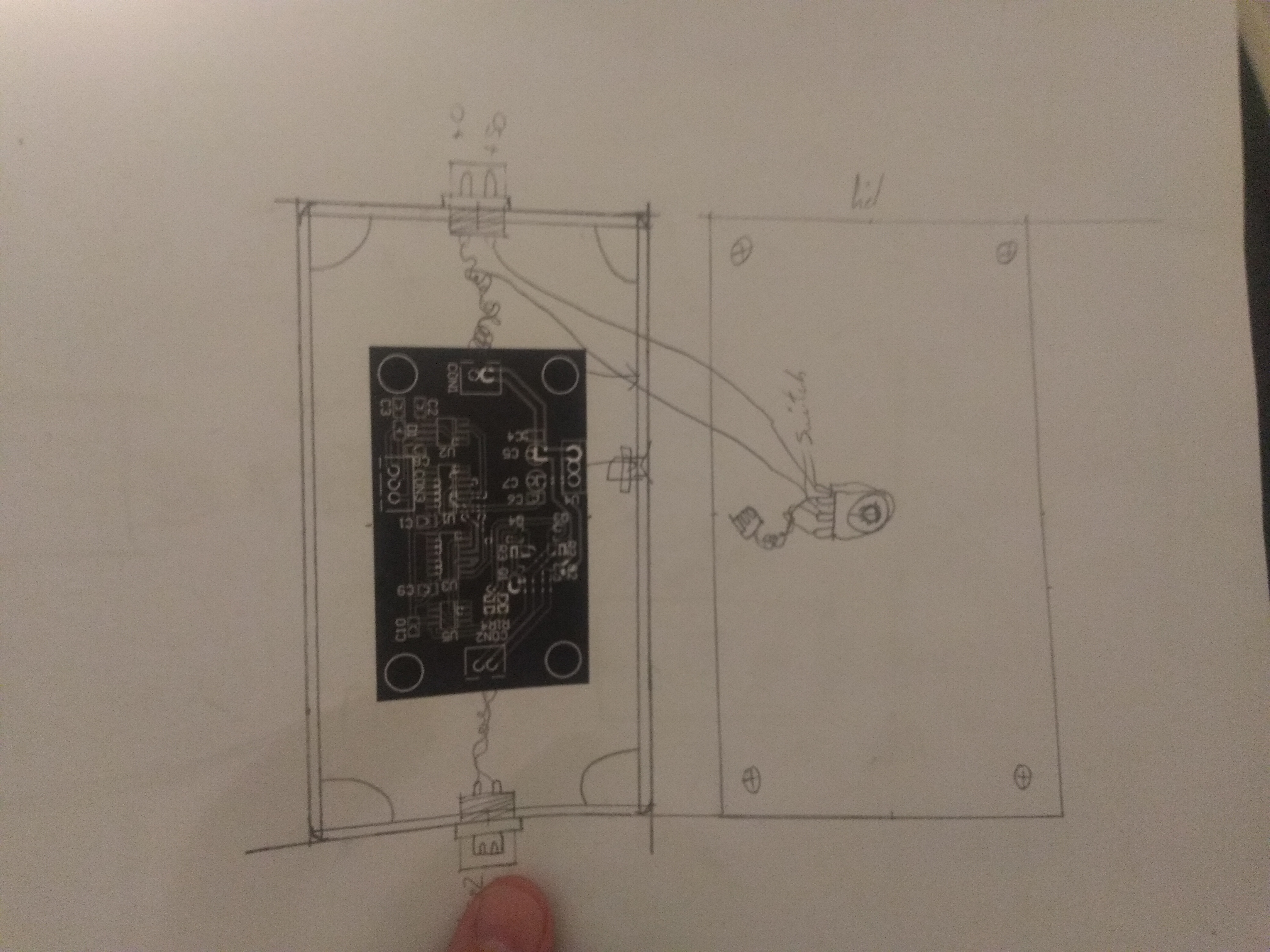
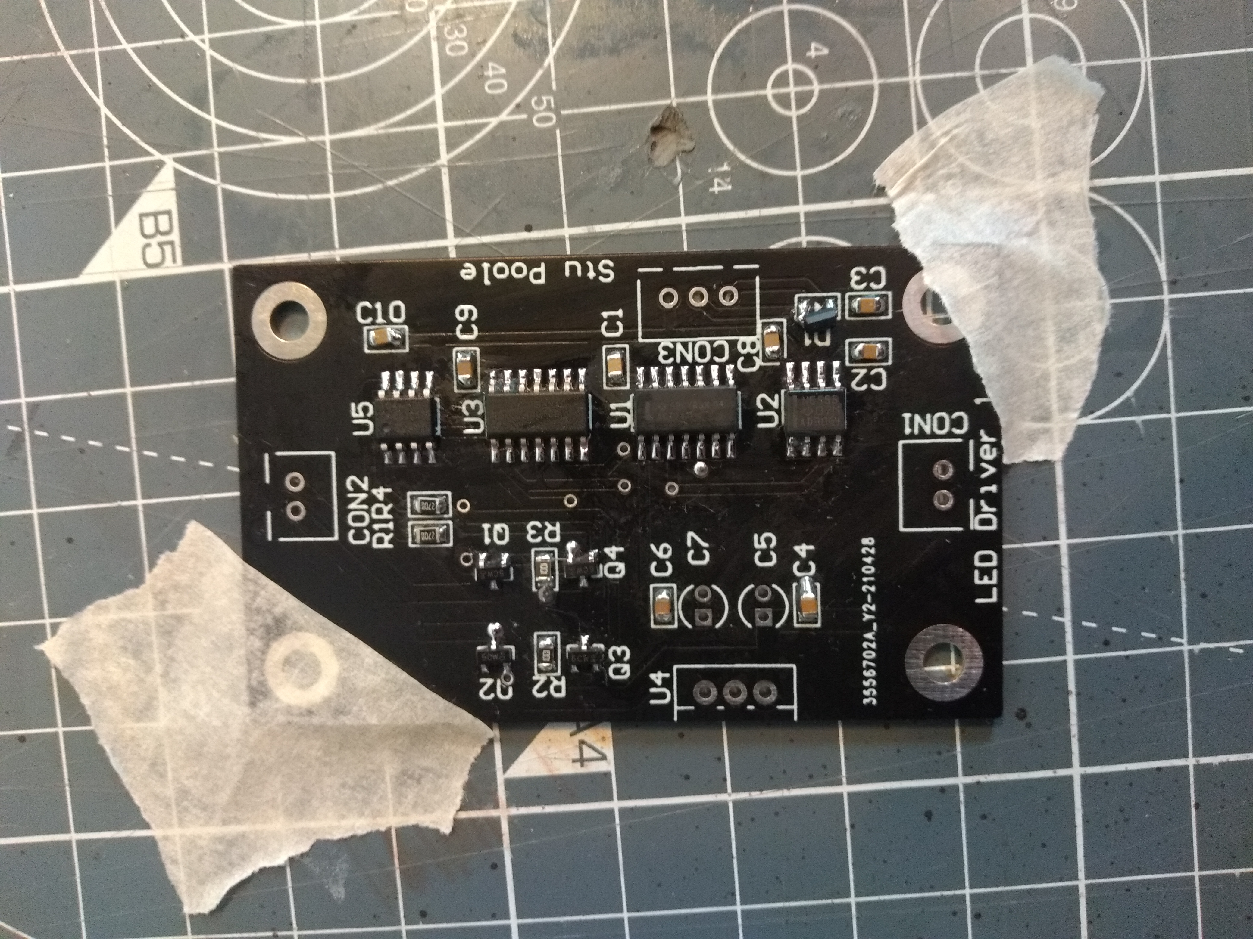
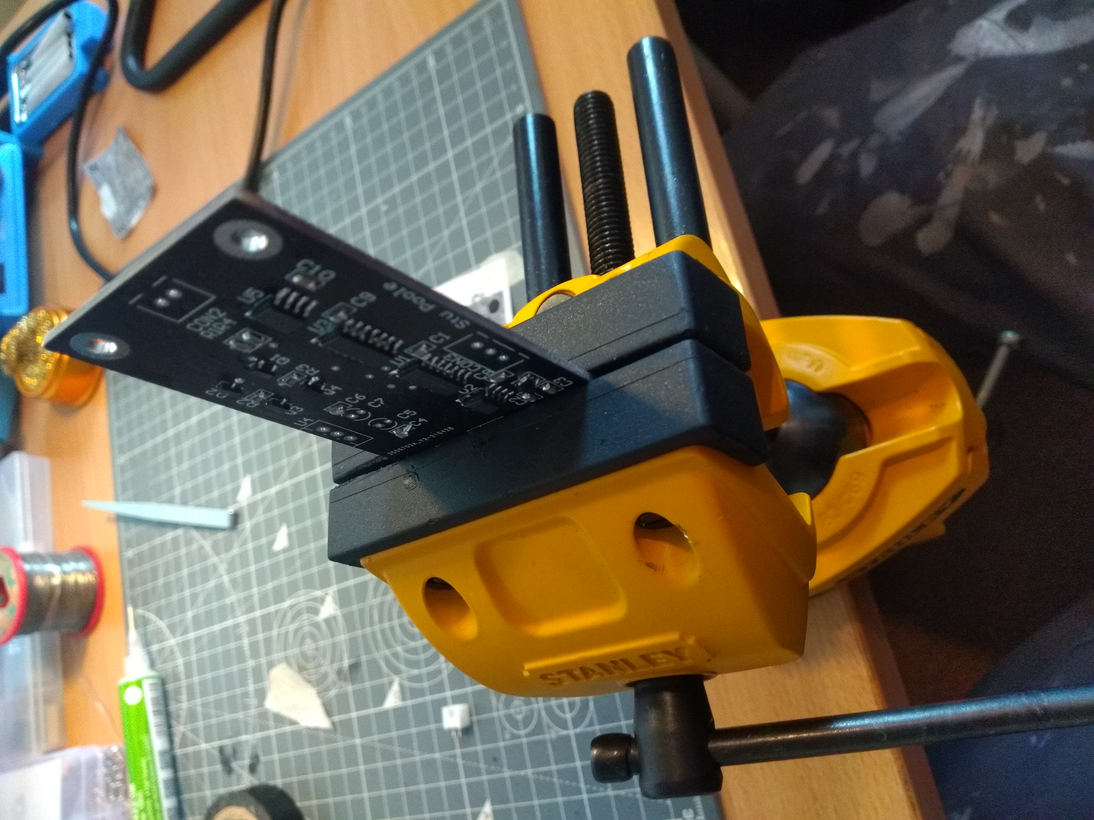
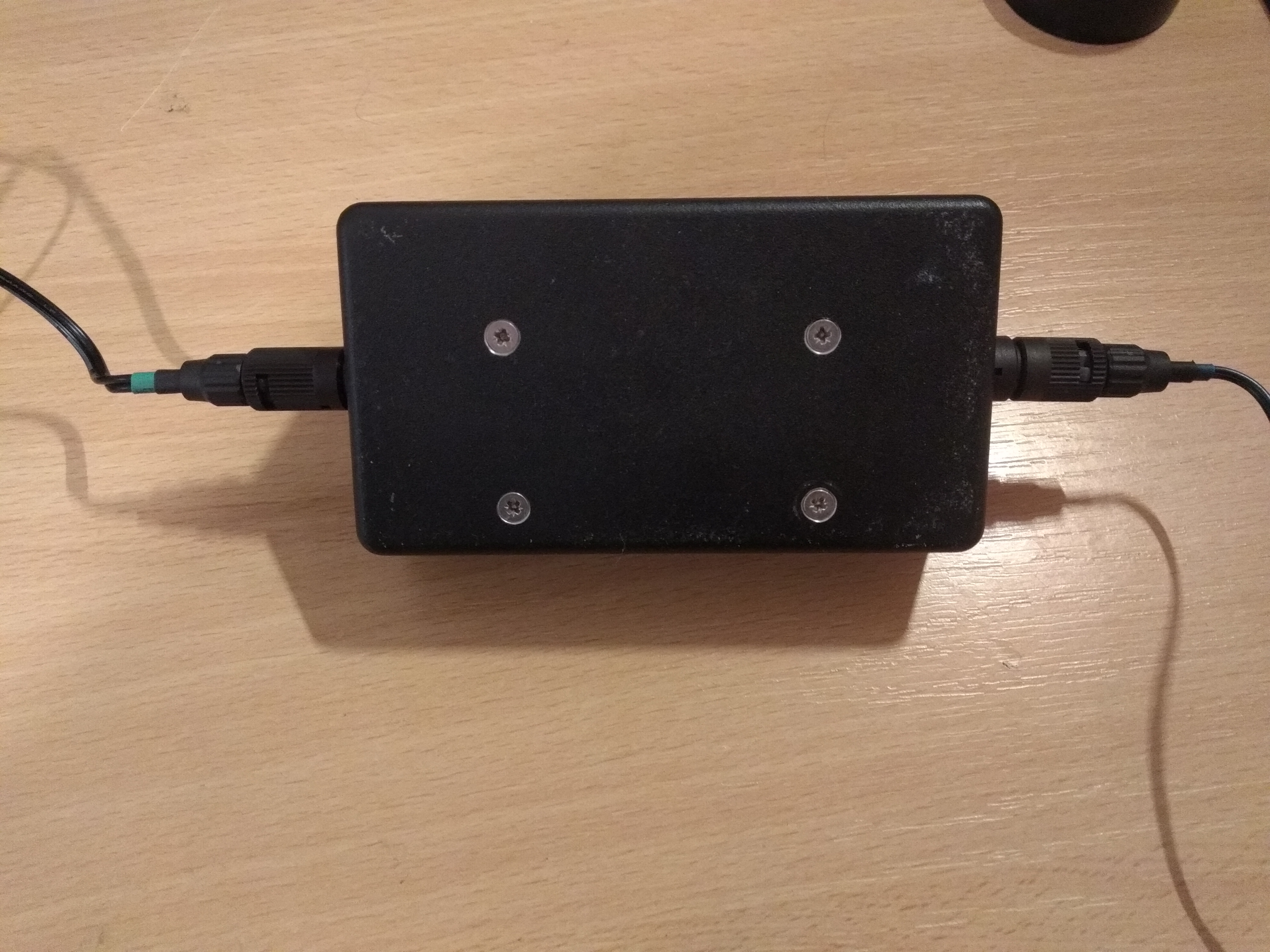
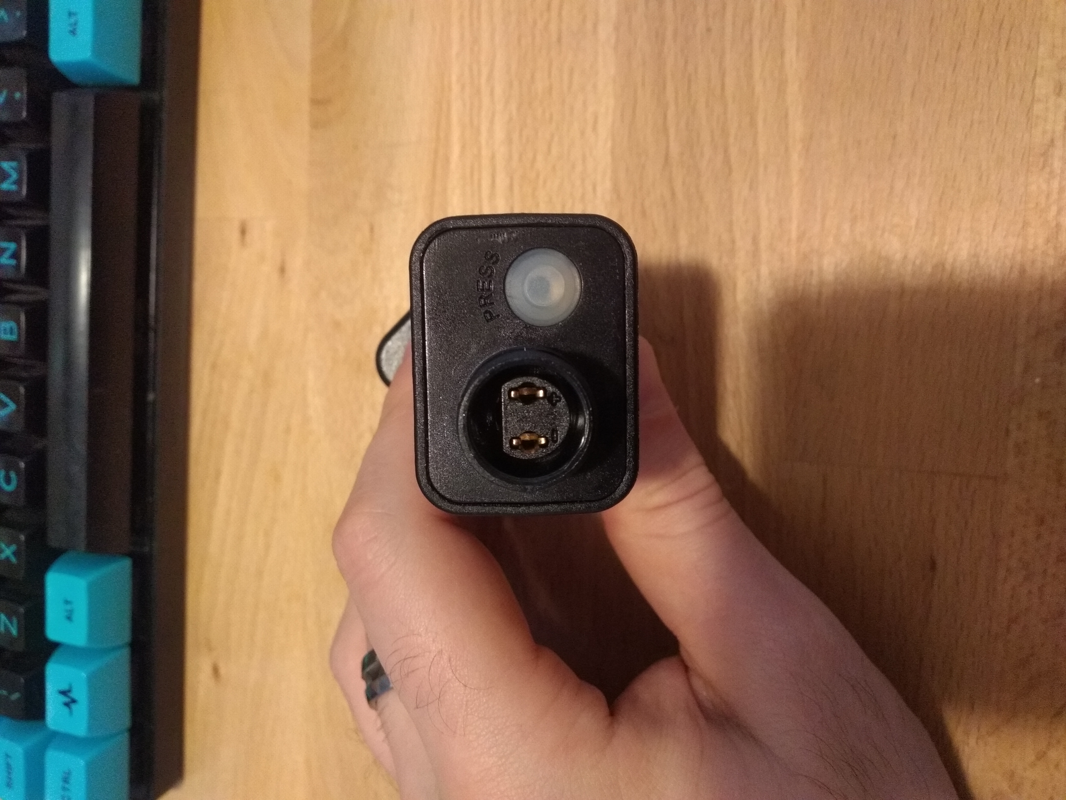
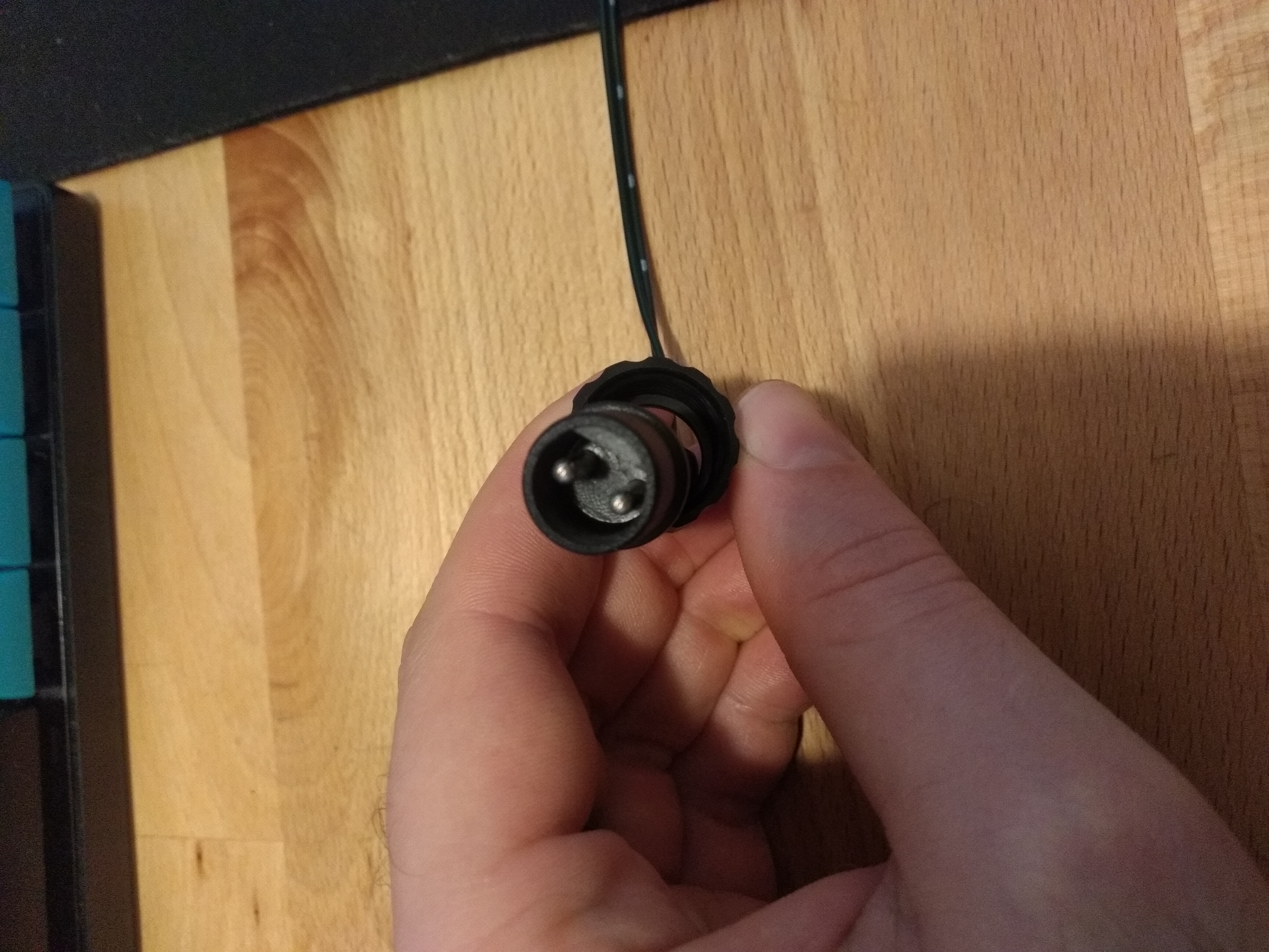
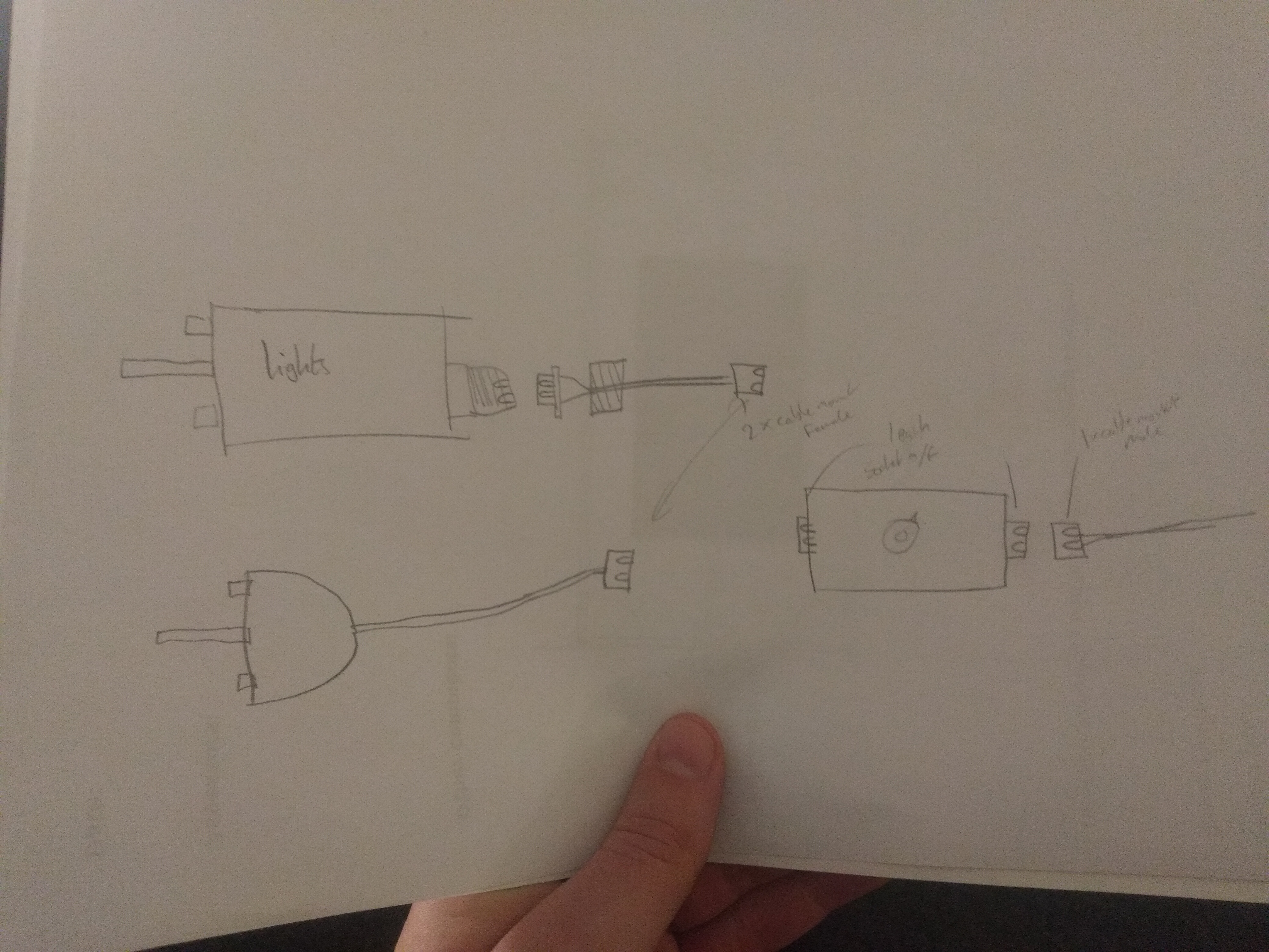
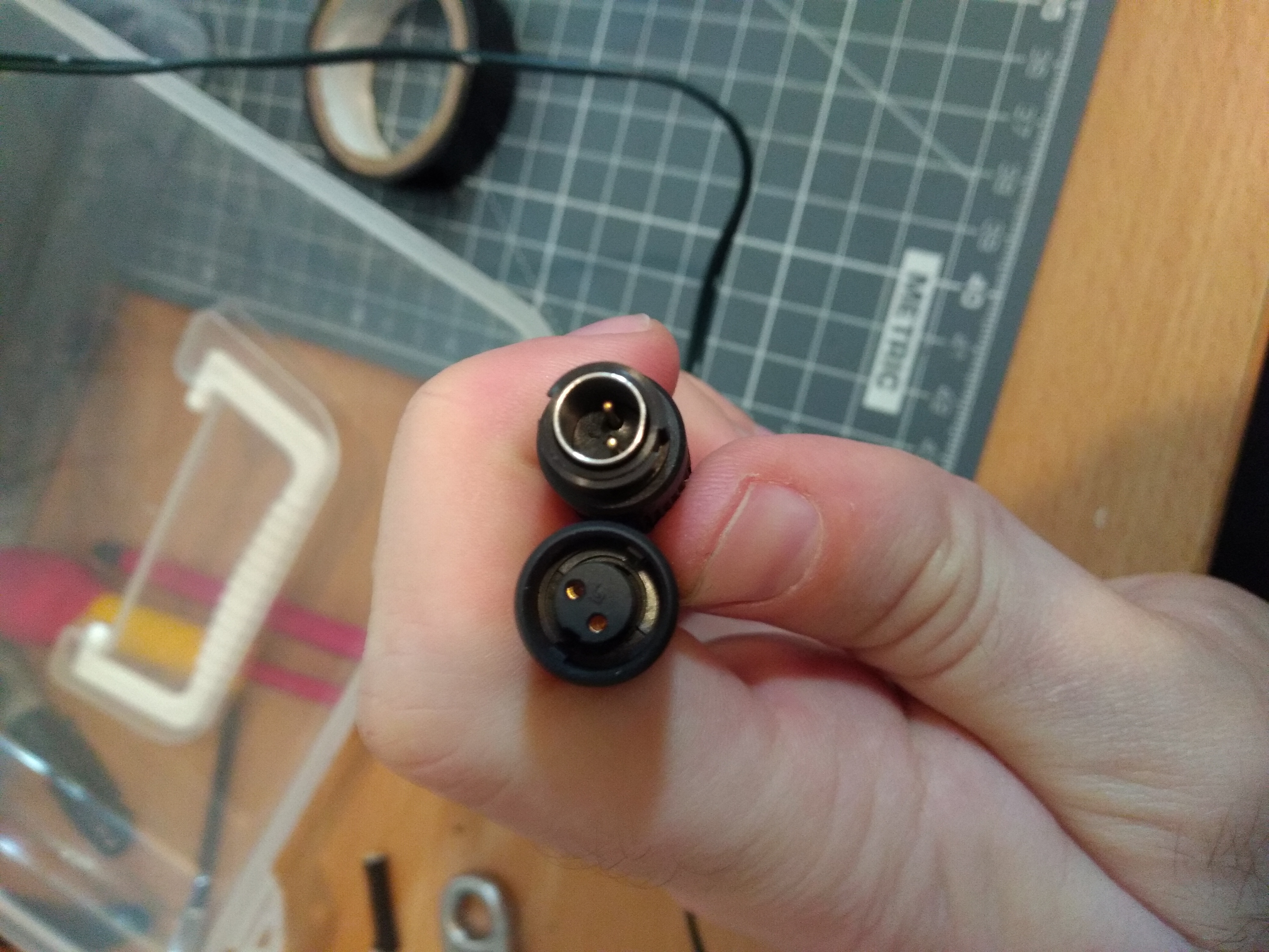
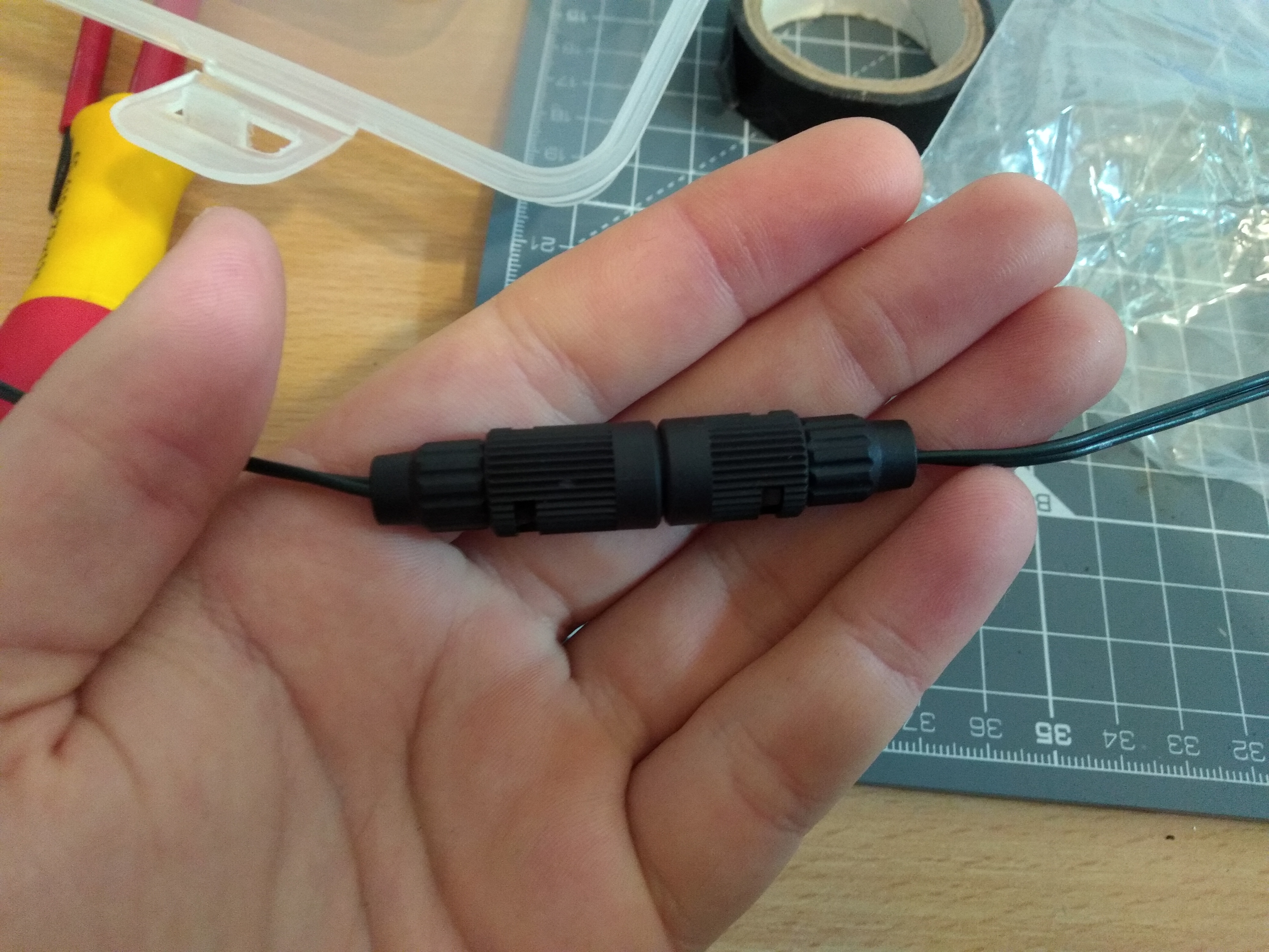
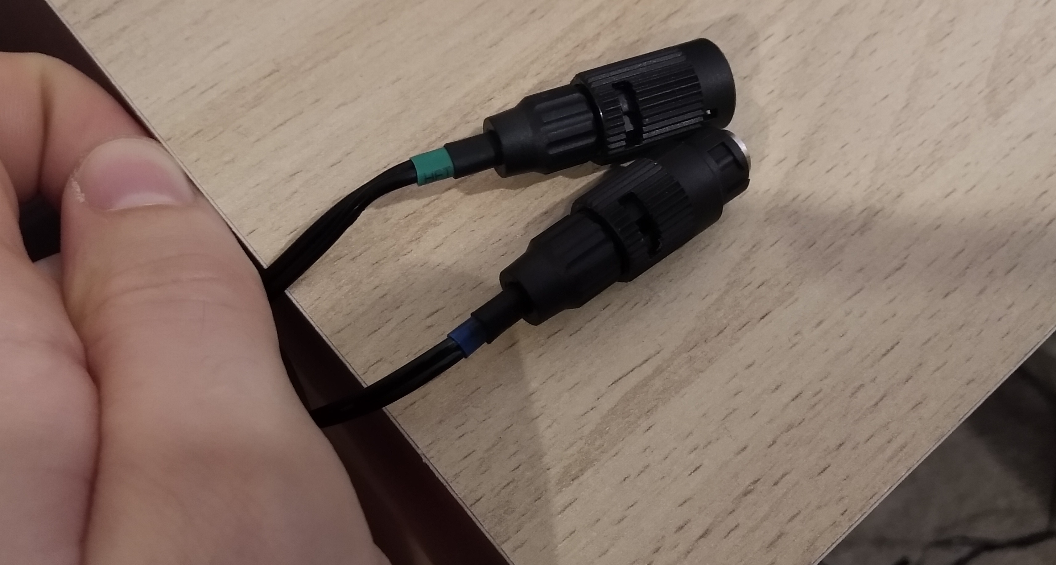
I designed the circuit in Altium Designer 2020, and made all the IC footprints myself, to make sure they were uniform. I only made one mistake in this process, and labelled the LED diver's right hand side legs wrong (1,2,3,4,8,7,6,5 instead of 1,2,3,4,5,6,7,8 in CCW direction). This is fixed in the downloads below. I ordered 0805 diodes on ebay and received a different family of package entirely. I managed to bend the leads and solder it on sideways but was very annoyed. The regulator did not fit under the lid and so the top was cut off. In hindsight, I could have added leads and mounted it anywhere else in the box. These were the only botches on the board, three neat bodge wires, trimmed regulator and a sideways diode. JST connectors were used throughout and, apart from the cheap potentiometer, the parts are all name-brand. To make the connections, mini circular connectors were used, all with a satisfying click. It is not possible to incorrectly connect the lights to the input or the PSU to the output but it is possible to connect the original PSU to the input pins of my box and that could be catastrophic for my circuit without polarity protection.
The potentiometer I chose has a built-in SPST switch which would normally be fine but for these LEDs, the AC pickup from the wiring in the house causes the lamps to glow very slightly, only visible in very dark conditions. In a future revision I would add polarity protection on the input. I have spent many hours searching for a DPDT or SPDT switch with the same form factor but the one I could find was discontinued in 2019 or 2020. There is one company (from my hometown, as it happens) producing a good solution, but I cannot find the exact one I need for sale in the UK. Ideally the potentiometer would be logarithmic to get more control in the dim regions.
Overall, the driver circuit works well and my first ever SMD soldering came out very well. There were a few teething issues, as is common with prototypes. With these ironed out, I believe I would have made something quite good, although altogether unnecessary!