Physics Research
Antiferromagnetic Spintronics and Magneto-optics
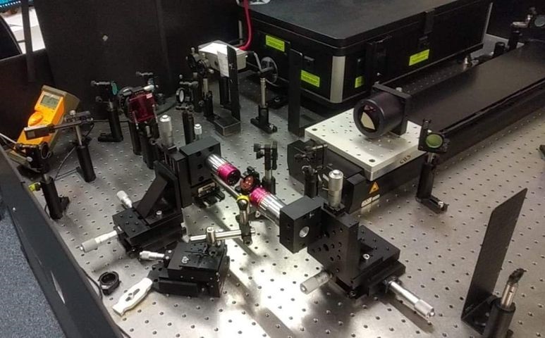
During my PhD in experimental spintronics and magnetooptics at the University of Nottingham, I have experience with many experimental techniques for magnetic characterisation such as transport measurements and magnetooptical measurements. My research focussed on studying CuMnAs as an example of an antiferromagnet (AFM) with promise in spintronic applications with it's relatively low resistance and ability to be switched electrically. My studies can be categorised into three main types of experiment: optical pump probe measurements, magnetoresistive electrical measurements and transport measurements (it would also be possible to break down my research into three major aims: to understand spin flop; to improve switching and electrical readout signals; and to understand the domain structure and domain formation in CuMnAs). Other smaller experiments were also conducted and I also spent a lot of my time assisting other researchers with their experiments while I was waiting for parts or equipment availability.
Spin flop is a sudden reorientation of antiferromagnetic moments which occurs above some threshold field when an external magentic field is applied along the easy axis of the sample. This reproducible and predictable method of reorientation of magnetic moments is ideal for demonstrating the magnetic origin of phenomena which may be applicable to new AFM characterisation techniques. Before studying spin flop using neutron diffraction, the full volume extents of spin flop were not known. By using magnetic neutron diffraction to detect the change in amplitudes of diffraction peaks, the full thickness extent of spin flop was detected as 98 % at 8 T, increasing confidence in the use of spin flop as a test of characterisation techniques.
The optical pump probe experiments were performed with the aim of demonstrating asyncrhonous optical sampling (ASOPS) as a convenient and rapid way of characterising the anisotropy of an AFM sample by using a heating pump pulse to induce demagnetisation in the material which is detected as a reduction in the polarisation angle change induced resulting from the Voigt effect. This same measurement process was also performed in collaboration with TU Dortmund, Germany, using aa delay line pump probe technique which detected spin flop as a change in the magnitude of this demagnetisation related Voigt effect polarisation angle change to unambiguously demonstrate that the signals are of magnetic origin.
The electrical switching possibilities of CuMnAs have been demonstrated previously (todo cite switching paper) and since then, there has been an upsurge in interest in CuMnAs and its possible applications. To this end, many studies have investigated the origins and possible alternative mechanisms for both switching and readout. Typically anisotropic magnetoresistance (AMR) is used as the readout signal to detect magnetic changes induced by current pulses but these signals are small. I performed various switching experiments and also used short-duration high-power pulses with simultaneous measurement to detect larger signal changes with the aim of detecting the steady state anisotropy of a sample without the need for magnetic fields to induce some changes. These studied led to the discovery of a new mechanism capable of generting much larger resistance change signals than expected.
Below are links to a paper summarising the neutron diffraction studies, a review article summarising AFM spintronics and the first paper demonstrating electrical switching and readout using CuMnAs.
Spin Flop in Uniaxial Antiferromagnet CuMnAs
For my MSci final year project, my lab partner and I investigated spin flop in antiferromagnetic CuMnAs. Spin flop is a sudden ninety degree rotation of the magnetic axis followed by a small canting toward the field in an antiferromagnetic material when the field is applied parallel to the antiferromagnetic axis, sometimes referred to as the "L-vector" or "Néel Vector". This occurs when the energy penalty of the anti-parallel moment is larger than the energy penalty for both moments to be off axis and slightly canted. The report linked below is a summary of our investigations and results showing that spin flop occurs at a relatively low field (around 2T) for our layer of CuMnAs. The report also included experimental simulations and temperature dependence of resistance measurements which were used to further probe spin flop in our material.
We explore some of the properties of the antiferromagnetic material CuMnAs. This is done through a combination of spin-flop measurements, zero field anisotropic resistance measurements and a series of numerical models. The spin flop field is measured in CuMnAs to be Bsf = 1.48 ± 0.04 T for one of our material samples, and Bsf = 1.44 ± 0.04 T for the other. The results from these works, when combined with XMLD-PEEM images, were used to determine the exchange energy density and anisotropic energy density in CuMnAs in two limits. The first model, derived by considering two moments in free space, yielded an exchange field strength of 220 ± 50 T and anisotropy field strength of 5±2e−3 T. The second model, considering a moments in the bulk, provided an exchange field of 80 ± 20 T and anisotropy field of 1.7±0.5e−3 T. In the course of our project also obtained a number of simulation results applicable to antiferromagnets more widely.
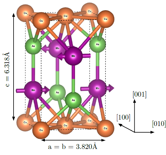
Unit cell of CuMnAS, the antiferromagnetic material used in the experiment.
Optical Determination of Contact Forces Using FTIR
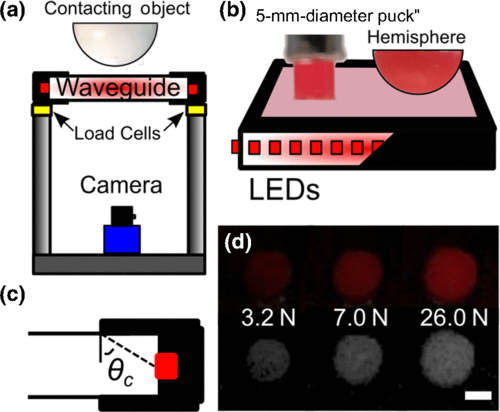
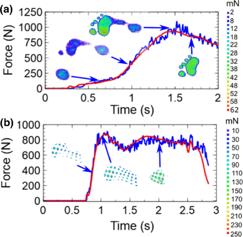 My supervisor at the time and I measured the contact forces of a sports shoe as a pressure map over time using a piece of perspex, some LEDs, some black tape and a camera. Some load cells were used to calibrate the system. It took much investigation to determine the properties which effect the brightness of light emitted from the waveguide, which was simply made from LEDs, perspex and black tape. The paper linked below details the experiment and derives the mathematics required to describe the interactions.
Abstract:
"A simple device based on the principle of frustrated total internal reflection is used to image the regions of contact between rubber objects and a large-area perspex waveguide. Measurements of the intensity of light scattered at the interface are found to depend upon the magnitude of the applied force, the mechanical properties of the contacting material, and the roughness of the contacting objects. The intensity-force response is found to have the same functional dependence irrespective of the position on the waveguide surface, but to scale by an amount that is proportional to the local intensity of light incident on the perspex-object interface. Once this spatial variation in intensity is calibrated, the waveguide can be used to perform optical measurements of the forces/pressures exerted on the surface of the waveguide and to generate spatial maps of the pressure at frame rates up to 200 Hz. The resulting optical force platform is used to measure the time-dependent evolution of the pressure distribution beneath a foot and a sports shoe during a foot-strike event. A simple theory is developed to describe the light-scattering phenomenon and to explain the relationship between the scattered light intensity and the applied force."
Measuring the Elastic Modulus of Thin Film Annuli Using capillary wrinkling
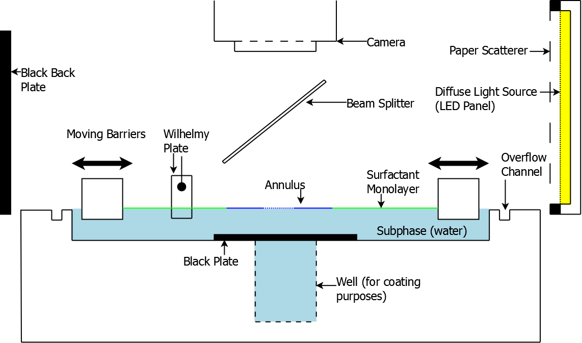
 For my 3rd year project/BSc dissertation equivalent, my lab partner Dom and I were paired up and set to work on improving some work done as a side project of Dr. David Farmer's PhD thesis. His project consisted of cutting annuli into ultra-thin films of polystyrene (<200nm) and floating them on water. The surface tensions on the inside and outside of the annuli were equal and opposite, generated by the capillary interactions at the inner and outer edges. A Langmuir-Blodgett trough, which is a device used to control the surface density of an immiscible addition to the subphase. In our case we added span 80, a surfactant, to the water outside of the annuli. The density of the surfactant could be adjusted using the trough, and the surface tension was simultaneously measured. The increasing density of the surfactant acted to reduce the surface tension down from the value of water to the value of span 80 by replacing the surface water with span 80.
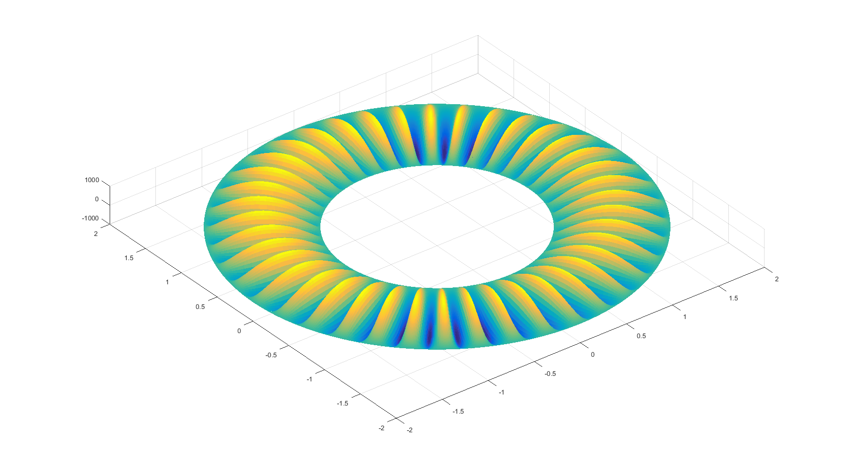
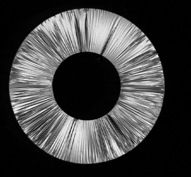 This lead to an imbalance of forces acting on the inner circumference and the outer circumference. When the difference in force was strong enough, the annulus would wrinkle according to an expression that was to be determined. The energy of the wrinkled and unwrinkled states would be equal at a certain force, referred to as the nucleation pressure, and a sinusoidal distribution film position was predicted. Unfortunately, defects in the films and surface tension lead to collapsing of wrinkles and disturbed the sinusoidal distribution. Instead, the wrinkles formed with stochastic position and varying amplitudes, leading to the aforementioned collapsing flaps.
The aim of the experiment was to count the wrinkles that formed using a high resolution grey scale camera and some image processing scripts in MATLAB to determine the number of wrinkles as a function of the difference in surface tension and to use this, alongside a theoretical prediction of the number of wrinkles, to extract the elastic modulus. The resulting equations, which were not derived ab initio and instead built upon David's empirical approach, were unwieldy and inaccurate. They always contained an offset, which we put down to defects and contaminants in the water such as dust and residual surfactants.
 After the project was completed and I'd had a break, I attempted to derive the form of the wrinkling from first principles using the 3D stress and strain relations and the known initial conditions and constraints. The resulting differential equations were intractable and required a lot of work and yielded similarly as horrendous equations as before. Because the equations are so unwieldy, the technique was decided to be infeasible and impractical, leaving it abandoned.
Thank you for taking an interest.
If you are interested in further information about any of these projects or are interested in offering me a chance to apply to your company, please do not hesitate to contact me using the form below. If you would like to see a summary of my projects and interests, please visit the highlights page using the link below: